Like so many of the projects we feature, this one started with a cheap eBay module purchase. In this case, it was a little Tesla coil that made decent sized arcs but wasn’t quite good enough. The result was a super-sized solid state Tesla coil with better results and room to grow.
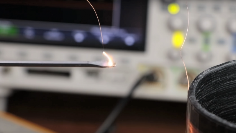
As [GreatScott!] discovered, the little eBay Tesla coil has a pretty neat design. The exciter is a Slayer circuit, a super simple one-transistor design. His reverse engineering revealed that the primary coil is simply a loop trace on the PCB under the secondary coil. Sadly, his attempt to replace the primary and reproduce the Slayer exciter resulted in anemic performance. What’s a hacker to do in that case except build a bigger coil? Much bigger — like “build your own winding jig” bigger. Twelve hundred secondary turns and an appropriately menacing-looking primary later, the results were — still anemic. It turns out the Slayer is just not up to the task. He turned to an inverter circuit that was previously used in a wireless energy transfer circuit, and we finally get to see a little of the Tesla coil magic. But wait! There’s more to come, as future videos will tweak the circuit and optimize the coil for better performance.
It’s no surprise that Tesla coils are a popular project around here, especially the musical kinds, from the tiny to the large. Music doesn’t seem to be on [GreatScott!]’s mind, though, and we’ll be watching with interest to see where he takes this build.


I’m just now in the middle of designing a dielectric heater, which is essentially a tesla coil.
A 6-turn primary to a 1200-turn secondary is 1:200 ratio, and if he uses 12 volts that makes 2400 volts at the secondary.
2400 volts is not much. If the breakdown voltage for air is 30kV/cm, that’s about 1/10 of a cm, or 1mm of spark.
I have the slightly-more-expensive eBay tesla coil (around $8) that has a wire going up around the coil instead of the PCB trace. It generates a couple (3?) of mm of spark with a 1:350 ratio coil.
A quick back-of-the-envelope calculation shows his secondary has an impedance of about 170k Ohms at his frequency of 400kHz (around 67mH). The secondary tank is in parallel, with Xc = Xl at resonance so the tank impedance is about 85k Ohms overall.
2400 volts into 85kohms ohms is 28mA, which is 67 watts. The coupling factor might be 0.2 or 0.1, so the secondary is putting out somewhere between 6 and 12 watts of energy.
This seems consistent with the output he’s getting.
Are these calculations correct? I’m trying to design something similar, and would like to know if I’m misunderstanding any of the concepts.
Oh BTW, this is a neat project, and I really like the clear explanations and drawn diagrams. Not dumping on it at all, and the video technique is superb!
I don’t know about the other data, but you can’t just use the ratio of primary to secondary turns to estimate the output voltage. A tesla coil is not a tranformer. Energy is transfered over multiple cycles and can build up way higher voltages at the output then this simple formula would suggest.
Um.. Yes you can. The coil is quite literally a transformer, and the input turns vs output turns gives you a *very* high ability to estimate the output voltage — provided you know the input. It’s one of the many benefits to them, as to digital solutions — Highly predictable.
Indeed! And in fact, the transformer ratio will be smaller than predicted because not all the magnetic flux of the primary goes through all the coils of the secondary, so the multiplication is likely a factor of 2 or more smaller than the transformer formula predicts (since it uses the assumption that all the flux goes through all the coils).
Hm…
If not all the flux is going through the secondary, wouldn’t that mean that you could draw an equivalent circuit where the secondary coil would be split into two coils? One that is 100% coupled to the primary and one that is decoupled from it. If that is the case aren’t you driving a coil through a transformer which could charge the parasitic capacitance at the end of (full) coil to a higher voltage than at the coupled coil (the transformer)?
Wikipedia seems to support my believe:
https://en.wikipedia.org/wiki/Tesla_coil#Output_voltage
Correct, it’s the resonance and the amount of energy stored in the system that dictates the potential voltage.
I think I remember reading somewhere that pvc is not suitable for Tesla coil builds… Had something to do with dielectric constant of the material creating large losses or something like that.
It can be a little counter intuitive, things conduct that you wouldn’t normally expect and things you’d expect to conduct, conduct in very different ways, if you’re not used to high voltages and high frequencies.
The windings don’t look very neat. The trick to avoid overlapping is to make loose windings first and then run one’s nail to shift them into place tightly. I’ve made a 2″ 1400 turn coil with zero overlapping using an even cruder setup. It wasn’t easy, but I’m proud of the result.
Doing it by hand can take a while. Very therapeutic haha. A dot of super gluas you go can seem like a good idea but the fumes can be a bit messy and if the coil gets warm it can increase the potential for arcing. I agree loose turns and bunching them back up tight again can be a good way to go. I keep telling myself I’ll make a lathe like jig with a follower one day but I usually end up doing it in one hit by hand over the course of a weekend.
Tesla changed the way I’m attempting to view electric power
And the emergence of our New World Order.
I wish I could have known him!!!!!!
Just replace all of the parts and it works sort of better haha. Couldn’t resist. Fun read and it sounds like he learned a lot in the process :)
All quibbling over the construction parameters aside, I envy the penmanship/drafting skills on this.