
The current state of robotics, 3D printers, and CNC machines means any shade tree roboticist has the means to make anything move. Do you want a robotic arm? There are a dozen designs already available. Need an inverted powered pendulum? There are a hundred senior projects on that every semester. There is, however, one type of actuator that is vastly underutilized. Linear actuators aren’t ‘maker’ friendly, and building a customized linear actuator is an exercise in pain.
For their Hackaday Prize entry, the folks at Deezmaker are changing the state of linear actuators. They’ve created ‘Maker Muscle’, a linear actuator that’s fully customizable to nearly any length, power, speed, motor, or any other spec you could think of.
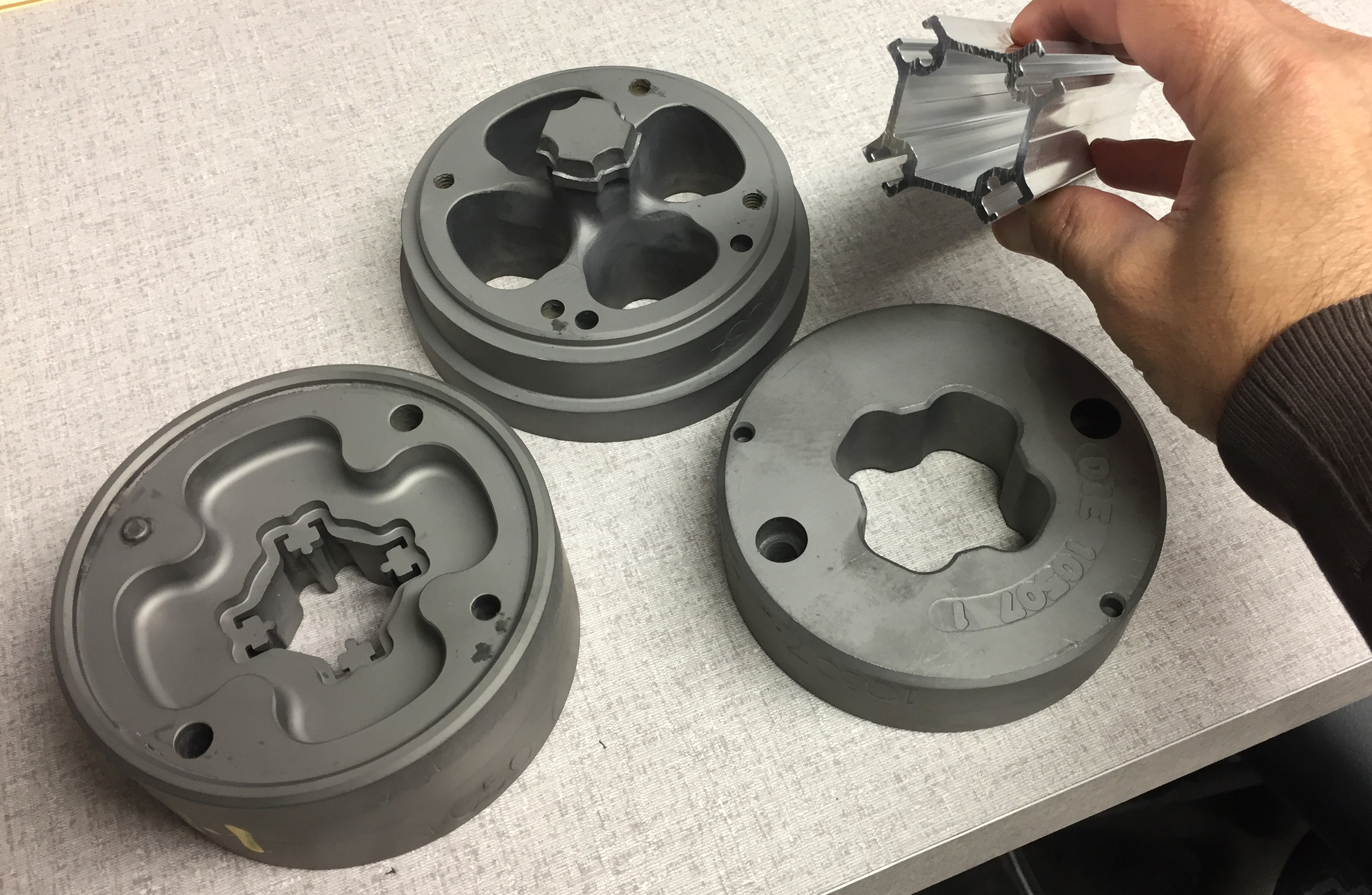
There were a few design goals for Maker Muscle. It must be modular, customizable, low-cost, and must allow for a lot of mounting options for use with t-slot aluminum extrusion. The answer to this is a completely custom aluminum extrusion. Basically, the motor mounts at one end, the actuator itself pokes out the other, and you can mount this device via the t-slot tracks around the edge of the extrusion. Think of it as the linear actuator version of MakerSlide, except instead of using this extrusion in CNC machines, it’s designed for moving shafts back and forth.
Already, Deezmaker has a working prototype and they’ve already moved onto a Kickstarter campaign for Maker Muscle. It’s a great idea, and we can’t wait to see what this neat product will be used for. You can check out a short demo video of Maker Muscle in action below.


I’ve always viewed linear actuators as a base component like a stepper motor. There are already so cheap and widely available that you never need to build one from scratch.
I’m not sure where you’re sourcing your actuators from, but “cheap” is not in the description of ANY that I’ve tried to buy.
https://www.amazon.com/s/ref=nb_sb_noss_2?url=search-alias%3Daps&field-keywords=linear+actuator So…
Those are cheap, but look like intermittent duty, limited life, non-environmentally protected components. Still, an interesting assortment.
Yes, 25% duty cycle but ip65 rated, for a 12v 20 inch priced a $88, some of the cheaper ones looked terrible and had a stroke of 2 whole inches.
Ryan, Thanks for the comment, but is there any actuators with steppers or some kind of accurate and consistent positioning at those prices? DC motors without encoders never land in precise positions. Cheap actuators seem to only go full extension and retract, not way to control in between or precise speeds.
I can see a second version of this coming as there are some issues preventing this from driving heavier loads.
1) They need to grind a flat onto the coupler end of the thread rod as that will vibrate loose otherwise.
2) They are using the bearing in the stepper motor as a thrust bearing and the actual stepper bearing is not intended for thrust. A new design could have an external thrust bearing, perhaps at the opposite end to the stepper.
3) The design if the actuator nut (like ball-screw nut) will leave it with poor lubrication and then wear causing backlash.
All the same, for light loads, it’s perfect except for the wiping motion of the nut removing the lubrication.
What is even more innovative though is that extrusion. Normal T-nut type extrusion holds the bulk of the planar material at either perpendicular or planar with the mounting surface. Ideally that bulk of the planar parts of the extrusion should be at 45 degrees to the mounting surface.
If they take one more step and make a double version (like a double XX) that has two mounting points for the mounting surface then they will have solved one issue that plagues common 3D printer designs. Current designs have very poor triangulation of not only the end structure but also within the components such as extrusions. This results in poor rigidity and susceptibility to trapezoidal distortion of the end structure. This is most often solved by using much thicker and much more expensive extrusion when a thinner, cheaper extrusion with different profile geometry would do the same job.
Yeah, cant use the stepper for thrust, there is a wave washer on the rear bearing which will deflect when you push on the shaft. That could be really annoying.
Link to the kickstarter if anyone is curious https://www.kickstarter.com/projects/deezmaker/maker-muscle-worlds-first-customizable-actuator-fo?ref=nav_search
What it needs is an inline planetary gearbox with bearings to take the axial thrust loads. One problem with most electric linear actuators with gear reduction is they mount the motor at 90 degrees or ‘fold’ it around the side.
Then stuff has to be designed around that motor sticking out. If you want to use an electric actuator to replace a hydraulic cylinder, if there’s nowhere for the motor to fit, you either are stuck with the hydraulics or you’re doing some rework on the equipment.
Planetary gearboxes develop lots of backlash as they wear.
Your mention of a hydraulic piston made me wonder about a peristaltic driven hydraulic linear actuator. For low loads it would have a high degree of accuracy and an extremely small backlash.
IME peristaltic tubing wears out really quick if you have the tension tight or run at high back pressure. Might be fine for art installations and some hobbyist applications but it’s not a terribly long term.
Diaphram pump?
Hope they can reduce the cost to $20/m
It’s no good, go back to god-damn steam!
I’ve always shopped at Surplus Center for cheap actuators; http://www.surpluscenter.com/Electrical/Linear-Actuators/