Ever wonder what’s inside a surface-mount inductor? Wonder no more as you watch this SMT inductor teardown video.
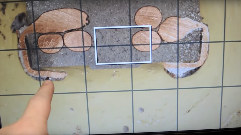
“Teardown” isn’t really accurate here, at least by the standard of [electronupdate]’s other component teardowns, like his looks inside LED light bulbs and das blinkenlights. “Rubdown” is more like it here, because what starts out as a rather solid looking SMT component needs to be ground down bit by bit to reveal the inner ferrite and copper goodness. [electronupdate] embedded the R30 SMT inductor in epoxy and hand lapped the whole thing until the windings were visible. Of course, just peeking inside is never enough, so he set upon an analysis of the inductor’s innards. Using a little careful macro photography and some simple image analysis, he verified the component’s data sheet claims; as an aside, is anyone else surprised that a tiny SMT component can handle 30 amps?
Looking for more practical applications for decapping components? How about iPhone brain surgery?
[via Dangerous Prototypes]


Interesting but I would have been more interested in seeing how the marked value compared to a measured value with a good LCR bridge. IMHO the entire video kind of fell apart at the end with what I would consider less than accurate measurements of the coils and what seems to be an assumption on the permeability of the core. A good measurement would have been more interesting to me.
You could try it yourself and do a quality measurement, if you have the equipment. I’d be interested to see the result.
Or you could just read the datasheet. Inductors typically have pretty wide tolerance bands (like 20%; I’m assuming it’s down to variations in the core material) and some funky variations in performance wrt frequency due to self-resonance, but it’s not like the manufacturers habitually lie about their performance.
This isn’t about the manufacturer’s claims about their components, in the video he comments about if they sold you a real part or not. So more like, is it a genuine and capable part, or is it going to melt itself off the PCB?
Had a gaming-grade grade video card where an inductor literally burst into flames :D
Seems like the whole concept of significant digits was lost here; measure the diameters very exactly and then just throw in a permeability of 8? A great primer on how NOT to do measurements.
And explain exactly nothing about where that value of 8 came from. Not to mention the leap from wire diameter to ampacity — that depends completely on the ability of heat to flow from the wire to the environment, the ambient temperature, and the maximum allowable temperature of the material around the wire, but we’re just gonna pretend that 1.8mm diameter means 30A.
It seems like a lot of work to get the geometric measurements to then just pull the rest out of your ass.
mumble, mumble, mumble…
Hee, still online?
Goldiloppers And The Three Bearloders