All over the world, in particular in underdeveloped countries, people die every year by the thousands because of floods. The sudden rise of water levels often come unannounced and people have no time to react before they are caught in a bad spot. Modern countries commonly have measure equipment deployed around problematic areas but they are usually expensive for third world countries to afford.
[Benne] project devises a low-cost, cloud-connected, water level measuring station to allow remote and central water level monitoring for local authorities. He hopes that by being able to monitor water levels in a more precise and timely fashion, authorities can act sooner to warn potentially affected areas and increase the chance of saving lives in case of a natural disaster.
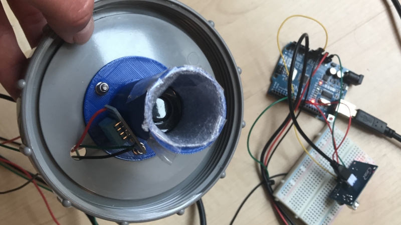
At the moment, the project is still in an early stage as they are testing with different sensors to figure out which would work best in different scenarios. Latest version consists essentially in an Arduino UNO, an ultrasonic distance sensor, and a DHT temperature/humidity sensor to provide calibration since these characteristics affect the speed of sound. Some years ago, we covered a simple water level monitoring using a Parallax Ping sensor, but back then the IoT and the ‘cloud’ weren’t nearly as fashionable. They also tested with infrared sensors and a rotary encoder.
They made a video of the rotary encoder, which we can see below:


A vertical pipe with the top closed and the bottom in water will have it’s internal air pressure change in proportion to the water level change. Have a tall pipe set in concrete with a horizontal passage for water flow (self cleaning) and put the electronics and solar power on the top, out of reach of people and water. This system is hard to block enough to matter or break, and uses less parts. BMP180 + ATTiny + (solar panel, charge circuit and battery) and a radio module of your choice. See the story on HAD recently about mesh networks and cheap modules.
In proportion to the water level and the outside air pressure.
And I don’t think it will be that straightforward to compute too. Air is compressible so water can move up the tube. Measuring the pressure inside (and outside) the tube will just give you the difference in height between the water outside and the water in the tube so you still need a way to estimate the height of the water inside. From gas laws you could compute the volume (and thus height) of air inside the tube and back compute the height of the water inside. BMP180 gives you pressure and temperature and you could determine the initial number of moles, but you can’t be sure that the number of moles won’t change over time, IMO. Air diffuses through water.
Yeah that is the point, do all the hard maths and testing up front in development and have the least complex system in the field so that it is cheap and robust. Also it is the rate of change that should be alarming not the actual volume, think about it.
You have to first determine what’s causing the change though.
Just to be more contrarian and because I forgot it: evaporation of water will also affect the pressure inside the pipe. Is the pressure increasing sharply because of a flood or because of particularly warm water being sloshed inside the tube? Probably need to solve a differential equation for that, psychrometry only gives equilibrium conditions. Barring that, the setup itself is like a piston; with water doing work to compress the air. It would most likely damp/filter/slowdown the pressure change to water level change you’re expecting to observe.
IMO, math is also part of the system and should also be as simple as possible.
Good maths doesn’t break and scales very well, a naive design that uses more parts than it should doesn’t have the same level of economic sanity.
If the tube is truly airtight, and if it is open under normal conditions, the math is simple. About the internal pressure will be about 0..1 ATM gauge per meter of water above the bottom orifice, assuming the water is fresh. Salt water is a bit heavier, and will give readings that are a bit higher than the actual level. Muddy water may have a similar effect. If the orifice is pointing downstream, then fast moving water will pull a slight vacuum, which will lower the reading a bit.
So, getting a truly accurate reading might be challenging with the closed tube, but it sure seems like a good approach for getting a depth estimate that is accurate enough for giving a flood warning.
I tried range sensing with an ultrasonic module just like that. The readings from the module were all over the place so I created a window for acceptable readings and averaged about 30 acceptable readings to get one result. It was never any better than about +- 15mm.
Makes me wonder if the module I was using is faulty. I was using it in a room and varying it’s distance from a wall.
How about a vertical pipe with a float which has a long thin gray-coded strip protruding upwards from the float’s top center? Some simple optical reader near the top of the pipe reads the gray code, so knows how far down the float is.
A big issue with water level for streams/rivers etc is the harsh environment.
Out doors sun wind rain huge temp fluctuations.
And I sent me places the water level regularly varies my a number of meters.
Not to mention floating debris colliding with the sensor
I know from being out bush that the water soaks into ground for a while before it flows. By the time it gets downstream or is running from a mountain it has built up quite a backlog.
It’s not the level of the water that you watch. If you see it consistently rising at an increasing rate then a flood is eminent.
How about a potentiometer whose shaft is connected to a float.
USGS has info of interest, including several different sensor types. Dig a bit and you’ll find technical docs.
https://waterdata.usgs.gov/wi/nwis/current?type=flow
A potentiometer will not hold up very long in a dirty, harsh environment. For the same reason, anything optical will fail very quickly.
Ultrasonic sensors need to be exposed to the environment to function; dirt can get in the fine mesh in front of the sensor.
If you really want to use a float, I would would put a magnet in the float and use an analog hall sensor to measure the position.
Another option would be a capacitive measurement, but again, fouling might be a problem.
I would consider using a number of NTCs. Usually, you would supply a low current to the NTC to prevent self-heating. In this case, I would use the self heating property to determine if each NTC was submerged in the water, by measuring the current trough and voltage across the NTC, which allows you to calculate the temperature. The obvious advantage would be zero moving parts, while the obvious disadvantages would be the fact that it is relatively power-hungry, and has an inherently low resolution (you need one NTC for each level).
I think this is a very good idea except for the electrolysis that would occur due to the DC voltage across the PTC (or NTC). You could make this much cheaper with simple cheap diodes like 1N419 or 1N4148 as long as you remove the opportunity for electrolysis.
I was thinking more of a long tube with an air flow sensor as the rate of change is more important than the static quantity but this has moving parts so I think your suggestion is far more refined and suitable to the harsh environment with that one caveat about electrolysis. Perhaps using a silicone sealant would allow this to work … or something that seals against water and has a low thermal mass.
Perhaps to solve the problem of moving parts you could have a long tube (perhaps metal) and at the top a sensor made like this …
I tube of much smaller diameter to amplify air flow that has a very low powered heater in the middle and two temp sensors, one above center and one below (or make it horizontal to get rid of bias cos heat rises) then there are no moving parts, the parts exposed to water can be a solid rigid pipe and it could still quite easily measure rate of change without bothering with static values.
I went the ultrasonic way using a cheap Chinese car bumper sensor (made for harsh environments already). I did temperature compensation (read from a DS18B20) and 5-value moving average in software and voila! accurate to 5 mm – distance to water surface in open air.
You may be interested to check out https://github.com/DAI-Maker-Lab/tepmachcha — the hardware has been running in field locations in Cambodia since last August without any major difficulty, and similar units have been deployed in Honduras and Indonesia.
I created a very similar system in NE Ohio in the spring of 2015. It uses a Raspberry pi to acquire the data from a ultrasonic sensor positioned above a stream/creak behind the place I work at. It has been running ever since. The statistics can be viewed directly from the pi, for testing purposes. The data it collects is pushed to a outside web server for public viewing and notifications. My web site skills are a bit rusty but here is a link to the site http://water.fredmartincarguys.com