For all the press WiFi and Bluetooth-connected Internet of Things toasters get, there’s still a lot of fun to be had below one Gigahertz. For his Hackaday Prize entry, [Adam] is working on an open source, extensible 915 and 433 MHz radio designed for robotics, drones, weather balloons, and all the other fun projects that sub-Gigaherts radio enables.
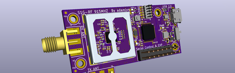
The design of this radio module is based around the ADF7023 RF transceiver, a very capable and very cheap chip that transmits in the usual ISM bands. The rest of the circuit is an STM32 ARM Cortex M0+, with USB, UART, and SPI connectivity, with support for a battery for those mobile projects.
Of course, you can just go out and buy an ISM radio, but that’s not really the point of this project. [Adam] has come up with an excellent board here, all designed in KiCad, all while flexing his RF muscle. There are RF shields here, too, so it’s far more than just a design challenge, this is an assembly and sourcing problem as well. It’s a great project, and an excellent example of what we’re looking for in The Hackaday Prize.


Hey Hackaday you should have a look at FaradayRF
https://faradayrf.com/network/
Far more interesting that the internet of shit :)
Like this ?
https://hackaday.com/2016/10/31/put-that-amateur-radio-license-to-use-on-915-mhz/
S1G-RF is not targeting IoT, its goal is to be an open source high performance long range sub 1 ghz radio for whatever project or application the user has in mind. With the right modifications to the firmware I wouldn’t be surprised to see users setting up the S1G-RF to work like the FaradayRF. My personal interest lies with UAV telemetry and automotive remote applications.
All that being said the FaradayRF is a great board and the S1G-RF is not trying to compete in anyway with it, my board is just another one with some similarities. Its funny you mention the Faraday because I know the designers and have worked a few engineering tips from them into the PCB design, both of them are really smart dudes, I recommend falling the on twitter.
I love Kicad, it has its own problems but I hope it get better
I love it too! As someone who uses Altium professionally (at my place of work, I’m not a billionaire) I have to say KiCAD is pretty close and in some ways is more fun to work with, Altium is better with library management but I find KiCAD is perfect unless you are managing 1000s of components for multiple hardware products.
If the ADF7023 has Root Raised Cosine filtering on TX like ADF7021 then this could be used for a DMR/D-Star hotspot like the ZUMspot does with ADF7021+STM32F103C8.
Hi there, if you wanna leave this same comment over at the project page, I can totally look into this and get back to you there, that way the comments/interaction will serve as documentation to others with similar interests as yours!
Why is there a big hole in that RF shield?
And why is the 10-pin ARM debug connector placed so close to the board edge that you can not fit the IDC connector that is wider than the pin header, if you put the board in a case?
see my below comment, mistakenly didn’t reply to yours.
What you are looking at is the mount for the RF shield which is soldered to the PCB, the actual RF shield snaps onto that mount so it.The debug connector is so close because I like small PCBs, though its going through a bit of tweaking before I send it to OSHPark next week. I have a few errors here and there and I can take that time to place the connector better.
As for being able to be put in a case, I’m not there yet with the design. Overall this board is meant to be a subsystem to another and be embedded with other electronics in a device, so I didn’t design it to be fitted in a standalone case. Back to being “not there yet” this is just a prototype, who knows if the second rev will be better for fitting in a case as a standalone device, I haven’t decided. I’m focusing on confirming the circuitry and getting it functional before I add more features and capabilities.