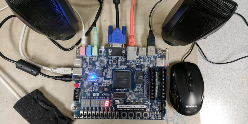
Cornell Students [Sean Carroll], [Gulnar Mirza], and [James Talmage] designed a realtime pitch shifter to run on their DE1-SoC and controlled by its ARM core.
The team’s goals were to pitch-shift the left and right outputs independently, to produce chords using the original voices as well as the pitch-shifted ones, and time-delayed pitch shifting. All of it is controlled on a VGA monitor through a simple GUI, allowing users to create lots of different effects by layering the different options.
Under the hood they made use of dual circular buffers to do the pitch shifting, reading in the sample and then using simple fixed-point arithmetic to modify it, then running the signal through a Butterworth filter to clean up artifacts.
The project was built as part of [Bruce Land]’s ECE5760 class. If you’re looking for more DE1 goodness, you’ll find excellent projects aplenty on Hackaday, including the LED Matrix Audio Visualizer from last year and Synthesizing Strings on a Cyclone V, among many others.


It’s a nice project to be sure, but I expected a much better audio quality. Back in the nineties, I used an Amiga 500 with an 8 bit sampler and a crappy microphone in a tape recorder and it was much cleaner. That on a lowly 7MHz 68000 processor :) The software was called Technosound turbo II released in 1993.
and how. i wondered why they didn’t give any information about the pitch shifting technique, and now i know.
Well, it is a university project. Being a university student myself, I often would like to work more on a given project, but time is of essence and one cannot throw time at a project as one likes. University / College is not a walk in the park …
It’s impressive. Do not forget that not everyone has a backgorund in signal processing. In their writeup they also said, that they just wanted to try another approach.
And, don’t forget: For every project done, there’s documentation to be done. Often it is 80 pages for a simple project like that. A lot of nerves and time go into the documentation rather than the project.
That’s pretty much exactly what you do when you build a pitch shifter with https://puredata.info/.
i really like the idea of producing chords. it sounds a bit like ring modulation. always nice to hear a pretty lady talk about tech stuff.
Very cool, nice touch with the control interface as well. I’ve always wanted to do a project like this on an FPGA.
My university has a whole bunch of these DE1 boards that are only used for the Logic & Digital Design class final project… which is only as complicated as making a digital clock that displays on the 7 segment display built into the board.
Neat proof of concept. I think the GUI was a nice touch, but sound quality was disappointing.
Seems to me that the input audio signal is simply being resampled at the output. I’ve used an XMega and a few lines of code to accomplish this effect. The input ADC clock was constantly feeding samples into a circular buffer. The output DAC clock was variable, and would read the buffer at a different sampling rate, producing the effect. Not true pitch shifting, and also suffered from the same ring modulation artifacts as this project.