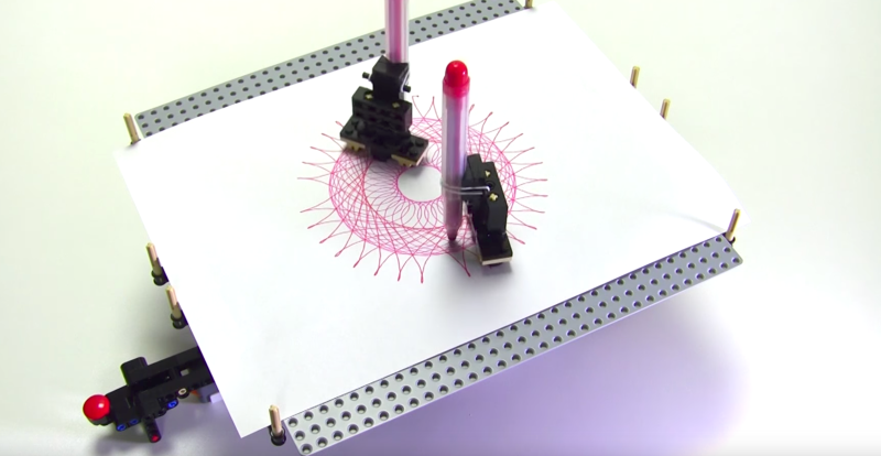
Master LEGO builder [Yoshihito Isogawa] has been on a roll lately, cranking out a number of robots that make drawings reminiscent of the classic Spirograph toy. For instance, he built an elegant drawbot out of LEGO elements, seen above. At first glance the monicker “spirograph” seems wrong, because where are the gears? However, [Yoshihito] has them stashed underneath the sheet of paper, with magnets controlling the pens.
 His drawbot consists of a platform (cleverly, an inverted LEGO plate) upon which a sheet of paper is laid. One or two pen holders, each with a pair of magnets underneath, rest on the sheet of paper. Beneath the plate, two pairs of spinning magnets rotate around a double layer of 11×11 curved racks, which then play the role of the classic spirograph rings. An EV3-controlled motor powers the whole thing.
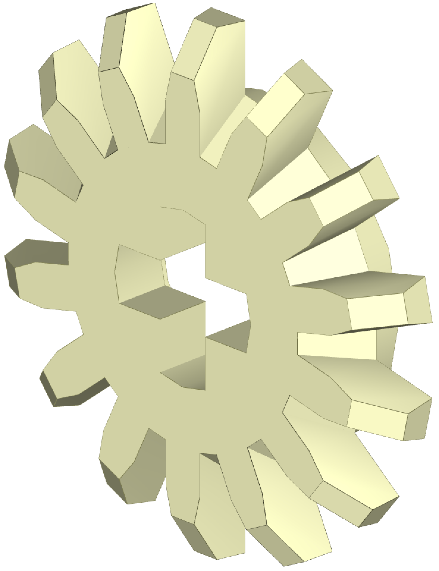
He also makes use of an obscure part–the 14-tooth bevel gear, last manufactured by LEGO in 2002 and even then it was mostly sold in part assortments intended for the education market. It’s so obscure LEGO doesn’t even provide the gear in their online building program LEGO Digital Designer, though (of course) the LDraw folks re-created it — it’s brick 4143 in the library, seen below.
Spirograph Gear Math
This gear becomes important in spirograph-style projects because tooth count is everything. There really aren’t that many spirograph designs that can be made with LEGO, because there are a limited number of gears and they mostly have the same tooth counts–the smaller ones sport 8, 12, or 16 teeth, medium-sized ones 20 or 24 teeth, and larger ones 36 or 40 — see a pattern? Such predictability may be great for a building set, but it doesn’t engender a lot of spirograph diversity.
When you compute the number of vertices in a spirograph shape, you take the least common multiple of the two gears (or sets of gears) and divide by the small gear. So a 60-tooth turntable turning a pair of 14-tooth gears has an LCM of 420, and you divide by 28 to get the number of vertices: 15. Remove one of those smaller gears and the vertices increase to 30. The challenge in creating new shapes with a LEGO spirograph lays in swapping in new gears, just like the original toy, and having more ways to come up with unusual gear ratios makes for more interesting drawings.
Another that makes the 14-tooth gear so alluring to [Yoshihito] is that it’s one of the few LEGO gears with a number of teeth not divisible by 4. Among other things this means the gear meshes with an identical gear at 90 degrees. Usually the gears have the same number for each quarter of the circumference and meshing becomes a matter of jogging one gear a scosh. This can be a problem because LEGO axles have a “plus” shaped profile, and you may not want everything on that axle tilted as well — having a 90-degree solution makes a lot of sense.
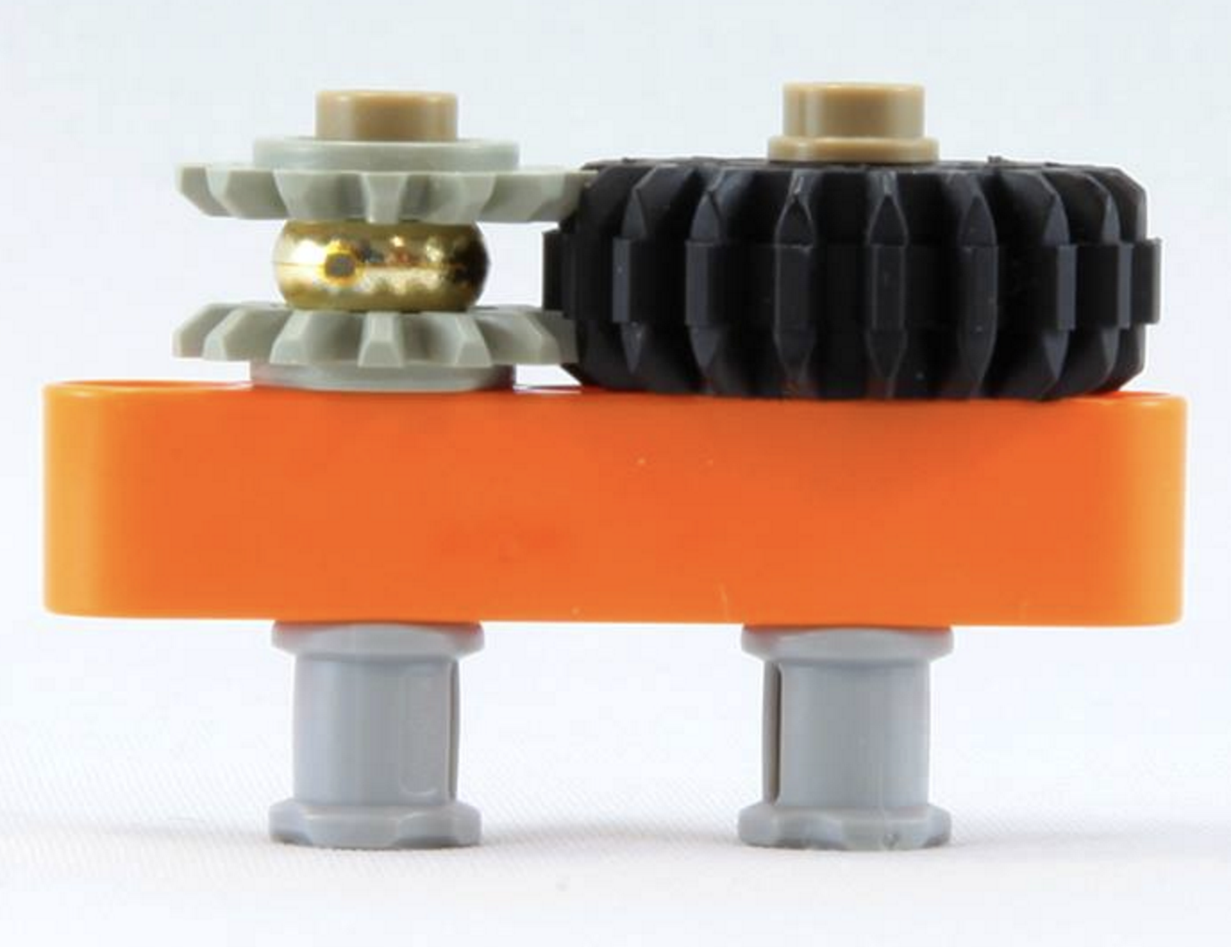 [Yoshihito] designs LEGO robots out of Isogawa Studio and has written several books on advanced LEGO techniques, published by No Starch. He specializes in small and elegant mechanisms — finding the perfect set of elements that work together effortlessly. You can see an example in the gear assembly to the right — a pair of the aforementioned 14-tooth bevel gears, turned into a normal gear with the help of that golden spacer, none other than a One Ring from LEGO’s Lord of the Rings product line. You can find videos of his projects on YouTube.
[Yoshihito] has released a number of variants of the spirographing drawbot. What’s next? Maybe a harmonograph?
Also see his equally impressive Circle Pattern Draw3r:


Heh. Is there anything one can’t build with Legos?
Apparently Legos. You can’t build Legos with Legos.
Patent infringement ????
Nice post HaD. The links you provided in the post help me (a Lego Noob) to start thinking about a particular design-case. Thank You.
I know next to nothing about Lego, and IMO I’ve found it hard to find the complex Lego parts that I see in “Advanced” projects like I see on YouTube (almost always there’s no info on where the parts came from, much less a BOM).
What I want to do…
Are there any Lego experts out there that can point me to a working project using Lego parts anyone can buy online that build an analog hours/minutes/seconds clock driven by a Lavet style single-pole/winding stepper? Ref.:
https://en.wikipedia.org/wiki/Lavet_type_stepping_motor
Or maybe the same thing using a standard multiple winding stepper which are AFAIK never available with multiples of 360/60=6 degrees per step? Ref.:
https://en.wikipedia.org/wiki/Stepper_motor
Yes, what’s needed will require gears and a telescopic 3x shaft to drive the clock hands.
Thanks, David
P.S., I know I’m a bit O.T. with my post. Apologies.
Cant help ya with your specific requests, sorry, but I can tell you that a lot of the projects use ‘Lego’ as a catchall term for the family of toys produced by the Lego Group. You have the usual Lego blocks everyone knows and loves and gives to little kids, there is also an advanced line called Technic that had simple gears and motor control, that in later years got the Mindstorm upgrade to build/program more complex designs. This project uses the latter 2. The only standard Lego in this project is the inverted base/build plate the pen/s draw on.
@Hrmm,
Thanks for the reply.
You said, “…but I can tell you that a lot of the projects use ‘Lego’ as a catchall term for the family of toys produced by the Lego Group.” and “The only standard Lego in this project is the inverted base/build plate the pen/s draw on.”
That says a lot to me! And thanks for the history of the Lego thing as a brand.
So it seems these rather complex “Lego” projects I see on YouTube may only use a small subset of what are actually “Lego” brand parts and add third-party parts that are somewhat compatible with “Lego”, but have nothing to do with “Lego” commercial products at all?
Hmmm…
Best Regards, David
I can’t point you to a project right off, but it is definitely within the capabilities of lego technic.
The concentric shafts are the hard/exotic bit. I think the most straightforward way to manage that is with (inside to outside) shaft, 24-tooth differential body, large turntable.
As for the rest, a pile of common gears should mostly get you there (60:1 is a mostly friendly ratio, no prime factors over 5, and our differential also has friendly tooth count), with one exception: I think the turntable has 56 teeth on the outside — to cancel the prime factor of 7, you’ll need a 14-tooth (which as the article mentions is rare) or 28-tooth (available only as a differential or small turntable, I think) somewhere in the drivetrain. (Of course, you could also use another 56-tooth large turntable to cancel it, but that just seems silly.) Driving from the inside 24-tooth gear would be nicer, but we won’t have room with the differential passing through there.
This gearing tutorial should give plenty of information regarding shaft spacings, etc.: http://www.moc-pages.com/moc.php/383194
@ben,
Thanks for the reply,
I’ll have to dig further into this “Lego Technic” stuff. I’ve tried before but was unable to find a single “Official Lego” site where there a list of all the parts available in one place. I’ll try again. It’s been awhile.
You said, “The concentric shafts are the hard/exotic bit. I think the most straightforward way to manage that is with (inside to outside) shaft, 24-tooth differential body, large turntable… etc.”
Interesting, but I don’t get the concept. That’s not your fault as it is difficult to visualize what’s going on just from your description in words here on a simple HaD post.
One way around the complex gearing to make the “analog” Lavet prime-mover clock I described would be to split each hand (hrs,mins,secs) so they’re driven by three separate bi-steppers. The synchronization would be done electronically via a time disciplined micro-controller. Another advantage is the three hands can move fast to “calibrate” at a given time (say midnight) without the complexity of moving the single prime-mover repeatedly to bring all three hands together at a single time (a much slower process).
But the mechanical problem of the three concentric shafts still remains with the three simple-stepper solution just as it does with the single stepper prime-mover. I think that’s the biggest hurdle, especially if I try to do it with off-the-shelf “Lego” parts that others may easily purchase to duplicate an “Open” hardware design. I really don’t want any “3D printer” or “laser-cut” custom parts involved in this project.
Conclusion:
Ben, it seems you know your gears well when it comes to design. Are you a Mechanical Engineer. I’m an EE, but I know the basics of gear-trains from Statics and Dynamics in school, and from experience in practice. It would be nice to discuss this project with you directly. But alas direct contact is difficult if not impossible via a thread on HaD.
Anyway, thanks for taking the time to reply. I’ll think more about what you’ve said in your post. You’re time was not wasted by replying.
Thanks Again, David
You can even do it with Lego and Logo.
https://en.wikipedia.org/wiki/Logo_(programming_language)
If you need to find parts for Lego projects try http://www.bricklink.com.
You can get unobtainable gear ratios by adding instead of multiplying (using a differential). For example, my humble 1/5 ratio with only gears that don’t divide 5.
http://www.brickshelf.com/cgi-bin/gallery.cgi?i=1684451
About the 14-tooth bevel gear, you say “even then it was mostly sold in part assortments intended for the education market”. I beg to differ: it used to be the standard inner gear of all differentials for 14 years, and (as indicated on the bricklink page you link to) was used in 80 sets, most of which were very popular and not targeted at the educational market…. Just sayin’ :-)