
I have some aluminum building-set parts on hand and just got a second rotary tool, so I thought I’d try my hand at making a light-duty CNC mill—maybe carve up some cheap pine or make circuit boards. This post explores some of the early decisions I’m facing as I begin the project.
Of primary importance is the basic format of the mill’s chassis. Gantry configuration or put everything in a box of girders? How will the axes move–belts or racks? How will the Z-axis work, the assembly that lowers the tool onto the material? Finally, once the chassis is complete, or perhaps beforehand, I’ll need to figure out how I intend to control the thing.
On Actobotics
 The main building blocks I’m using to build my mill consists of a building set called Actobotics. The set includes a variety of beams, most especially the hole-studded channels you can see in the image to the right. They also dabble in a T-channel profile as well as mini-channels used for smaller projects.
The line also includes mounts for a variety of standard steppers, servos, and DC motors, plus all the clamps, adapters, bearings, and axles you need. Their entire product line works together and that’s sort of why I chose it–that and also because I had a fair amount on hand already.
However, this is purely for convenience. I’m not married to using other materials in this project and fact it would be hard not to. For instance, logic dictates it would need a bed of some sort. Also, intrigued by to Othermill’s acrylic side panels, I was considering adding something similar to my project to help add a little rigidity.
Actobotics follows two hole patterns simultaneously–0.770″ hole spacing horizontally, 1.5″ diagonally, with both 0.14″ and 0.5″ holes pretty much covering each part. This reduces channel weight and gives you a bunch of options for attaching things, whether native Actobotics elements or anything else. You can use a laser or CNC to mill custom connector plates that interact with this hole pattern, allowing to easily add Pi enclosures and whatnot to the chassis.
They have a fairly broad line of Actobotics parts at SparkFun.com or you can find them at ServoCity.com.
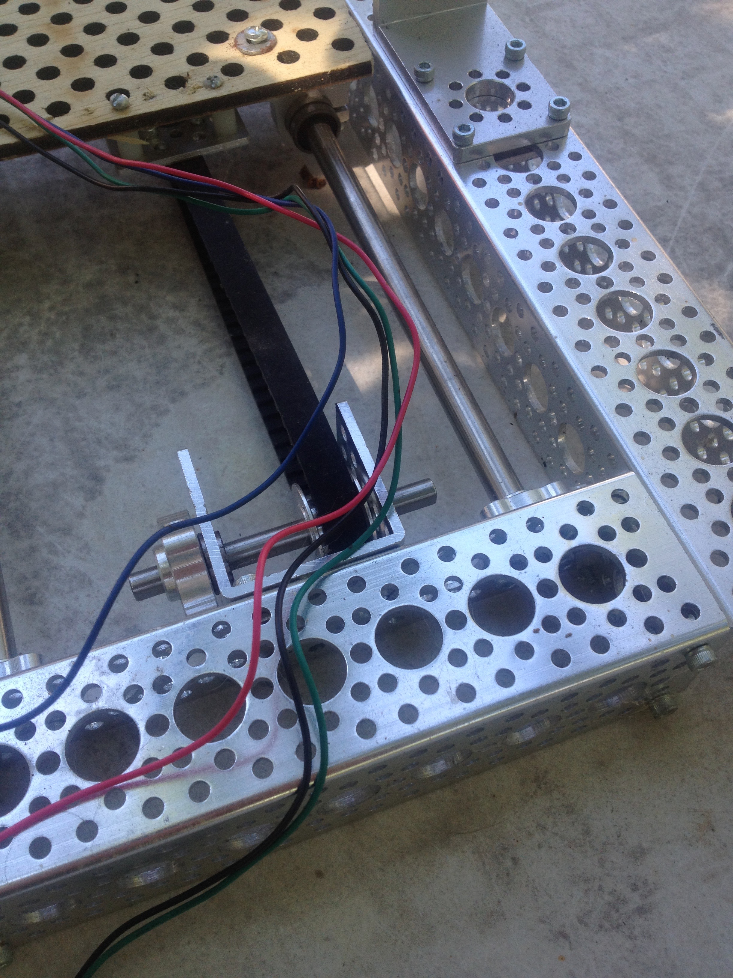
The Base I’ve Built
Okay, so I’ve already got a first draft of the base with a belt drive and stepper in place. You can see it in the image at the top of the page. I can change it and probably will. Still, it’s a good place to start.
My first thought was to go with a 4″ build platform. I built the base without necessarily thinking in terms of a bed–it was for a different project. The length of the Y axis was arbitrarily chosen based on the rods I had on hand–one footers. Working with it now, it feels like it’s too long for a 4″ platform. But that made me thinking, maybe I could have a rectangular build platform. Maybe 4″x 6″?
Then I realized there’s a way I can be scientific about this. The linear bearings offer around 10″ of movement as currently configured. Would that not suggest a 5″ build surface because the entire bed must cross over the X axis? The piece of wood I have currently attached to the bearings is 6″ wide, and it’s scraping the sides. Now I’m thinking a 5″ x 5″ build platform. While I can think of a few projects that I’d like to make that would be bigger; it’s the perfect size for what I have in mind in the near term.
The Theoretical Gantry
 The next step is to visualize how the Y axis will look and work. The gantry, if you will. They’re not all alike, of course. When talking about smaller desktop mills, beam structures seem to fall into two broad categories: the classic gantry configuration–a crane with supports on two sides–or else something of a box configuration.
Gantries usually employ a very heavy horizontal beam upon which the toolhead travels back and forth to make that X-axis magic. I’m thinking of an X-Carve Inventables as an archetype. Box-types–like the Othermill, for instance–have lighter X-axis support but there is more of a frame or box that surrounds the bed to provide the maximum amount of stability.
My first idea for the gantry involves a series of girders around a foot in height, allowing only a very modest Z height adjustment–just enough so I can change the bit without too much difficulty. One of my major concerns with using a building kit to make a CNC tool is the fact that the thing is likely to wobble, and wobble makes for poor-quality output.
Much of my opinion on the subject is colored by my experience with another CNC tool, my Makeblock Constructor 3D printer. Made from a kit, it consists of Makeblock’s signature blue beams with NEMA steppers and Open Source clone hardware. It put out some serviceable prints but there was always a nasty wobble to it. One of my future projects is to strengthen Horus, as I pretentiously call my printer, with some bracing beams and a nice heavy base–or maybe some Othermill-like acrylic panels. Anyway, this experience reinforces (ha) the notion that if I do create a mill, I want it to be as wobble-resistant as possible.
The Wobble Factor
My Constructor wobbles quite a bit. Screws come undone, and some of the parts are thinner than others. This is a reality I’m certain to face.
 Aluminum beams are very light. My mill will have to be bolted to a surface or it’ll vibrate off the table. Some of the most successful small-sized CNC mills employed very heavy-duty beams. One of the large mills we have at the hackerspace (seen to the right) has a massive slab of 80/20 T-slot, some of that 80×160 boat anchor stuff that looks pretty much indestructible. So you say steel is a better choice? Well, I don’t got any.
In addition to the frame not being steady, toolhead vibration is an other issue. I’ll need some kind of clamping mechanism (maybe 3D-printed?) to hold the shaft extender or the rotary tool itself if I go that route, with some sort of vibration damping pads.
Another factor could be the proportions of the mill. What I mean is, would low and squat make for more stability than tall and thin? The Constructor’s gantry rises a full 12″ above the build platform. Granted it’s a 3D printer where there is an expectation of, well, 3Dness, but even for that product it was probably too high.
I’m aiming to lift the tool the bare minimum to swap bits in and out, so I certainly wouldn’t want anything as tall as the Constructor’s gantry. Low and squat sounds intriguing, but with the lightness of the aluminum channel taken into consideration, I’m starting to think that more of a box shape is the way to go.
Next Steps
There are so many to-dos on the project I’m fit to bust a head vein. Gotta design the tool-holding mechanism and the rest of the chassis. Research CNC controllers. Build a heavy table or platform onto which to bolt the CNC. Decide whether to use the shaft extender or just the tool itself in a clamp.
So tell me, you loyal few who made it to the end of this piece, do you have any suggestions for how I could proceed, or stories of your own experiences? Bust them out!


Might not be stiff enough for a CNC cutter but it’d probably work great for a 3D printer or laser engraver system
Check out this awesome home-built 3DP: https://www.youtube.com/watch?v=p_Edbkpf8pE
this is my mini mill, worth a look if your wanting to do something like this http://imgur.com/gallery/hTqos
very nice, does that ABS block help stabilize it?
yeah, but the biggest thing that has helped me the most is spending 70 bucks to pick up a cheep spindle on aliexpress, i dont have any vids of it with the new spindle but its alot quieter now and not so weeble-wobbbly any more
Good upgrade. A dremel is the worst spindle for a cnc machine. I don’t know how model designs vary over time, but mine has one bearing around the spindle shaft that is held in place by soft rubber. In a cnc set up, if the cutter hits something hard, the rubber will cause it bounce around, making a messy inaccurate cut.
Do you have a cheap spindle you recommend?
Fill the extrusions with silicone and sand – that damps the vibrations quite a lot.
Aluminium bends/stretches about 3 times as much for the same load as steel, and twice compared to cast iron, so the load bearing cross-sections should be 2-3x the area to maintain the same rigidity, or, the profiles should be shaped so as to place the material further away from the neutral axis in the direction of the bending. I.e. instead of a square tube, a rectangular tube.
I’m drooling over those mills with the massive steel gantry.
I just have a hard time taking actobotics seriously with all the imperial units…
At the risk of feeding a troll; Precision is not affected by the unit that measures it. If it bothers you that much I’m sure they could give your the metric equivalents so you can work in your preferred units. Your control board should be perfectly able to work in picofurlongs if that’s your preference.
At any rate with these small lightweight mills cobbled together from surplus or cheap parts, you’ll be lucky (or have sunk considerable time into it) to get precision equal to a hobbyist level manual mill.
Conversion rate of 2.01168e-7 picoFurlongs to 1 mm; the math couldn’t be any simpler
Imperial (now American) length units have for some time been a metric-derived system, as the inch is now defined as being exactly 25.4mm. (Just look up “inch” on wikipedia.) So the obsolete units are also metric now – just obfuscated by a simple scale factor. Anyway, any of those historical artifacts can easily be converted, e.g. just run:
$ units
You have: 1 m/s
You want: furlongs/fortnight
* 6012.8848
/ 0.00016630952
Apropos the inch being based on the width of the king’s thumb knuckle, the obsolete Danish inch, called Tomme (thumb) is 26.15 mm.
American traditional units (because the empire has abandoned inches and feet for most uses) are completely accurate.
Because they’re referenced to the meter / defined in terms of the meter. Seriously.
That aside, because 12 has more factors than 10, inches are probably easier to use for sight estimation (I have no source for that opinion)
Even if the foot were still in reference to the last living king’s shoe size that still wouldn’t affect the precision or accuracy of a measurement.
Precision or accuracy have nothing to do with the definition of a unit (or it’s related law). It’s a factor of how precise your instruments are. The dividing engine that cut your standards matters way more than what the unit is.
Certain units may be handier for certain tasks but no one unit is inherently more precise or accurate than another.
>”because 12 has more factors than 10, inches are probably easier to use for sight estimation”
The inch doesn’t factor into 12 parts, but 8, 16, 32, 64, and 1000 parts.
Sight-estimating sizes at the scale of feet isn’t accurate down to the inch without the use of references. It’s very hard to just look at something and say whether it’s 2½” or 3″
Actobotics really helps people who can’t drill holes. Thank you Actobotics!
Great project! I’ve just started on the journey too and it’s great fun. I hear you about the expliding veins, lol! The last couple of days I’ve spent wrapping my head around the cam software. Camworks in particular, I can’t recommend it, its archeic, it’s buggy and you need lots of patience, even for a very patient person.
Anyway, here are some videos on my youtube channel:
https://www.youtube.com/watch?v=W1H0HDn1ex0
I went the openbuilds OX router way, based on ooznest mechanical kit, except it was all ordered from aliexpress. I wanted something I could easily upgrade, just like i did with my 3d printer. Get a kit to get started quickly and reduce the time spent hunting down parts and figuring out where goes what, although that’s also part of the fun.
Anyway, as chinese kits go, plenty of missing stuff, damaged parts etc so plenty opportunity to get creative.
I don’t like to be locked in or limited so I’ve trieD to get most of the checkboxes checked:
– wood routing
– pcb carving
– capable of machining aluminium, increases the ability of self replication and upgrades.
especially the latter requirement meant a sturdy machine, hence the ox, which is a beefed up (pun intended) version of the routy cnc which had its roots in shapeokos cnc machines as I understand it.
I’ve already modded my Ox by 3d printing the z axis plates with bigger holes, the belt tensioning system as I like my belts very very tight, from experience with 3D printer. I also 3d printed the odd spacer and a pen holder to test and calibrate the cnc before wasting wood, which has been great. Also printed limit switch holders to home the machine and prevent crashes.
I went with much more powerful steppers and drivers, and I’m glad i did. Nema23 3Nm 425 oz-in 3A steppers.
As for the spundle, I found a really good deal on aliexpress, a 1.5kW ER11 chuck spindle and matching vfd. It gives me plenty of power for the things I want to do and speed control means i can trade off power, noise, feedspeed etc. I went with the square housing version. I made a sturdy full length mount for it out of aluminium. It was relatively easy to tram and align.
The build height isn’t great though but it was made that way by design. Like you mentioned, the closer the router bit is to the gantry beam, the more solid the mechanism. I currently have only 40mm, but that’s because of the waste board height. I’m going to use 20×20 extrudions together with the 20×80 down through the center. Better clamping flexibility and it allows for much more build depth, up to 70-80mm. And also allows work pieces to be mounted vertically, for routing dove tails for example.
As for the controller, I just went with the planet cnc clone i got with the stepper motors. It’s an mk1 board and misses the tool probe connection input. Z limit probing is limited to single probing only, no array, warp or automatic corner location detection. I will buy the real thing from planet cnc once funding is replenished. I like the interface better than mach3, ymmv. It’s usb at least. A grbl arduino clone seems to be the standard choice for the ox. It’s cheap and seems to work well for most people. gcode sender software is much more limited though, less coherent opensource stuff, so more opportunity for hacking or wadting time depenfing on which side of tge fence you are.
Mach3 controllers also seem to be popular, with versions for usb as well. Cheap too, especially those with integrated drivers. But should one driver fail, you’ll need to replace the entire board, unless your soldering iron skills is proficient.
That’s great info! Thanks for sharing.