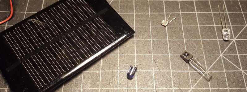
Arduino 101 is getting an LED to flash. From there you have a world of options for control, from MOSFETs to relays, solenoids and motors, all kinds of outputs. Here, we’re going to take a quick look at some inputs. While working on a recent project, I realized the variety of options in sensing something as simple as whether a light is on or off. This is a fundamental task for any system that reacts to the world; maybe a sensor that detects when the washer has finished and sends a text message, or an automated chicken coop that opens and closes with the sun, or a beam break that notifies when a sister has entered your sacred space. These are some of the tools you might use to sense light around you.
Photoresistor
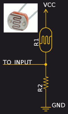
Also called the Light Dependent Resistor (LDR) a photoresistor is exactly what it sounds like; a resistor that changes resistance when exposed to light. This is probably the easiest to use and the hardest to break, so it’s great for beginners. Made from (usually) cadmium sulfide, it changes resistance from hundreds of thousands of ohms in the dark to hundreds of ohms in the light.
Hooking one up is as easy as creating a basic voltage divider circuit. You can then do an analogRead on the pin and watch how the value changes when the light level changes. This option is ideal for simple circuits where you are trying to detect the presence of visible or infrared light, but it’s very slow to react (hundreds of milliseconds), so it’s not good for data transmission.
Photodiode
The photodiode, also appropriately named, is a diode that changes the amount of current that passes through it with the amount of light. It can be used in two different ways. The easy one is photovoltaic mode, where the photodiode is exposed to light, the energy of the photons excites electrons which generate a voltage that you can measure to sense light level, or collect as in a solar cell. The other is photoconductive mode, where the diode is reverse biased. Without getting into the exact physics, this mode has faster response times, making it more useful for data transmission using light (like an IR receiver).
All diodes are photodiodes to some extent; some are just shielded better. Many remote control sensors will have a filter on it to allow only a narrow band of light through. Even an LED can work backwards, though not very well. The high level of variability makes it less than ideal for production or larger applications, but for a one-off it’s pretty slick. We covered the idea of LEDs as light sensors a couple years ago. We also saw that with the Raspberry Pi 2, a particular diode would reset the pi when exposed to bright light.
Phototransistor
If a photodiode converts light into current, then the next step is pretty easy. A transistor uses the amount of current at the base to control flow of electricity between the collector and emitter. Put the two together, and you have the photodiode acting as the base to control the transistor. The phototransistor can be either active, where the amount of light changes the amount of current flow in the transistor, or switched, where there is a threshold above which the transistor is on and below which it is off.
Phototransistors are used in remote control receivers because they are fast, easy to use, and made to filter out all but a very narrow light frequency range. Technically, the photodiode is faster, but both work well for IR receivers, and the phototransistor has the added benefit of gain, meaning it can achieve longer range. Consumer IR signals usually work on a carrier frequency between 36 kHz and 40 kHz, and phototransistors have switching frequencies up into the hundreds of kHz, making them ideal for this application. In this basic example, one IR LED is hooked up to a microcontroller, and a phototransistor is hooked up to a separate microcontroller, with only air between them. There are a variety of libraries available to do the communication, but from an electronics standpoint, this is the basic circuit.
Optoisolator
 Also known as the optocoupler, this is a clever device that combines a light source and a light sensor into a single package. If you’re familiar with ground loops, you’ll know what a pain it is to have two separate systems that are electrically connected. Sometimes it’s really nice to isolate the two, but still allow them to talk to each other. This is done with an optoisolator, which has an LED and a phototransistor or photodiode inside it. One system powers the LED, and the other system watches the phototransistor.
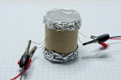
These are very handy if you have a high voltage system to which you have access, but don’t want to risk blowing anything up by connecting your Arduino to it to monitor status. These can be both digital (on/off) and analog (range of values), based on the application. You can easily make your own optocoupler by combining an LED and a photoresistor or photodiode or phototransistor together inside a light-proof case. The circuit is exactly the same as the previous circuit.
Photovoltaic Cells
You’ve seen them on your calculator and roof. These convert photons into electrons and generate a small voltage. It’s the same as a photodiode in photovoltaic mode because that’s exactly what it is. The only difference is surface area. For calculators, a small surface area can be enough to power the calculator (or charge up a capacitor or battery for short bursts). By sensing the voltage on the cell, it’s possible to detect the light level. Your outdoor light sensor could just include a photovoltaic cell, ESP8266, and battery!
If all you are doing is sensing the light level for a device that is usually powered, though, this solution is overkill. It’s probably best to keep photovoltaic cells for generating power and use other sensors for detecting light. Of course, we won’t say you can’t use them for transmitting low-quality audio.
Color Sensor
Just detecting the presence of light is sometimes not enough. Sometimes you need to know what color the light is. If you are looking for a specific frequency you can take a photoresistor and cover it with a colored gel and call it mostly good (except for white light, which would contain all the frequencies). This one-pixel camera is best suited for things like sorting M&Ms and Skittles, and is often found on assembly lines or other sorting tools. There are two ways to make a color sensor. The first is with a single photodiode and RGB LEDs. You turn on the red, capture the photodiode value, switch to the green and capture the value, and switch to the blue and capture that value. A red thing will have a high red photodiode value and low other values. This scanning approach is slow, though, so the other method is to have three photodiodes and a white light, with colored filters over each of the photodiodes. This way a reading of all three colors can be taken simultaneously. The photodiode will respond differently to the different parts of the spectrum, so some calibration after the reading is necessary.
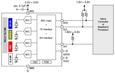
Here is a typical application circuit for a color sensor IC (The BH1745NUC from Rohm). It has 4 photodiodes, three of which are behind red, green, and blue filters. Those are then fed through an ADC and presented to a microcontroller via an I2C interface. Most color sensors do this because they handle the color calibration within the package.
CCD
We have photo sensitive resistors, diodes, and transistors so far. How about capacitors? The charge-coupled device (CCD) is the thing in your camera that captures an image, or the line on your scanner. It’s made of an array of tiny pixels, each of which has a tiny light-sensitive capacitor. When light hits it, a stored charge is built up, creating a voltage. Then a series of shift registers scans through the array of capacitors and measures the voltage levels, which correspond to light levels at each pixel. The bigger the array, and the more dense the pixels, the higher the resolution of the camera.
If you want to capture color images, you have two options. The first is to take a black and white camera, then bathe your subject in red light and take a picture, bathe it in green light and take a picture, and bathe it in blue light and take a picture, then combine those three images into one with each image representing a different channel. The other option is to get a CCD with three times as many sensors, each covered with a colored filter, and take a single photograph. We covered the technology behind CCDs in much more detail already, but the gist is that you use them for capturing images.
Which one is right for you?
Of course, it all depends on your application. For detecting simple light levels, go with the photoresistor. They are super simple, cheap, and robust. If you need something faster for signalling, upgrade to the phototransistor, which is not quite as fast as the photodiode, but the extra gain makes it easier to integrate into your project. For keeping your electronics separate from other electronics, use an optoisolator. If you need to do facial recognition to identify your dog to allow it through the dog door, use a CCD and send us a tip when you’ve completed the project. Bonus points if you use a large two-dimensional array of photoresistors to make a very slow low-resolution camera.


I though the transfer bandwidth of photoresistors was closer to 1kHz than 10Hz? But … yes, certainly still very low.
These are often used in organ volume pedal applications. Light thru a wedge shaped slot throttles the audio when dark, no other components needed. When they age they get real slow. You can hear the delay when flooring the gain and it rises over a second or two. Time for a replacement. RoHS has banned the Cd-sulfide type.
@echodelta: Do you know of a good replacement?
The combination of being a slow-reacting and resistive element is what all of those audio effects are based on. You can slow down voltage changes across photodiode/transistor with a capacitor, but then you’ve got to go through gymnastics to get that back into a resistance for use in (e.g.) the feedback loop of an op-amp gain circuit or filter.
I use tons of CdS cells (that I bought surplus, with a clean conscience?) because I can’t replace them easily, but the time will come when my old stash runs out. Know of anything?
Full-swing bandwidth? Or for small changes? Perhaps we should be discussing slew rate instead. :)
But yeah, potaytoe-potahtoe. They’re slow. (And temperature dependent. And exhibit hysteresis.)
I always love these “basics” articles, even though I know something (or even a lot) about the topic already, there is always some detail that I’m glad to at least be reminded of.
Wanting to sense light is what got me started in electronics. How far things have come.
I wonder if you focus light onto the ADC ref voltage pin that the resistance will shift enough to derive a useful measurement?
Loved the paper tube optoisolator. Heatshrink tubing carefully shrunk at just the ends should be simpler to implement. In a pinch, a short tube made from UTP insulation works too; just use a pair of needle nose pliers, or other means, to gently stretch out the ends so they will slip over the two components. Since not secured though, best used when inside another enclosure, e.g. a semi-transparent or translucent project enclosure.
Surface-mount LEDs with a dab of superglue fit nicely on the surface of an LDR. Cover in black electrician’s tape, or, if you’ve got it, black hot glue.
(And if you don’t have any black hot glue, get some black hot glue. It’s like Martha Stewart vs Marilyn Manson.)
What about LASCRs? I’ve got one of those floating around in my parts bin — got it Radio Shack when I was a kid, over 30 years ago. I need to find a use for it someday…