There’s little question that an oscilloscope is pretty much a must-have piece of equipment for the electronics hacker. It’s a critical piece of gear for reverse engineering devices and protocols, and luckily for us they’re as cheap as they’ve ever been. Even a fairly feature rich four channel scope such as the Rigol DS1054Z only costs about as much as a mid-range smartphone. But if that’s still a little too rich for your taste, and you’re willing to skimp on the features a bit, you can get a functional digital oscilloscope for little more than pocket change.
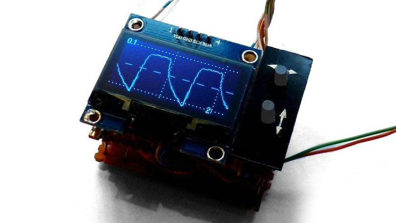
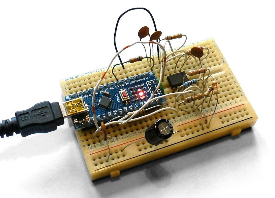 While there are a number of very cheap pocket digital storage oscilloscopes (DSOs) on the market, [Peter Balch] decided he’d rather spin up his own version using off-the-shelf components. Not only was it an excuse to deep dive on some interesting engineering challenges, but it ended up bringing the price even lower than turn-key models. Consisting of little more than an Arduino Nano and a OLED display, the cost comes out to less than $10 USD for a decent DSO that’s about the size of a matchbox.
But not a great one. [Peter] is very upfront about the limitations of this DIY pocket scope: it can’t hit very high sample rates, and the display isn’t really big enough to convey anything more than the basics. But if you’re doing some quick and dirty diagnostics in the field, that might be all you need. Especially since there’s a good chance you can build the thing out of parts from the junk bin.
Even if you’re not looking to build your own version of the Arduino-powered scope [Peter] describes, his write-up is still full of fascinating details and theory. He explains how his software approach is to disable all interrupts, and put the microcontroller into a tight polling loop to read data from the ADC as quickly as possible. It took some experimentation to find the proper prescaler value for the Atmega’s 16MHz clock, but in the end found he could get a usable (if somewhat noisy) output with a 1uS sample rate.
Unfortunately, the Arduino’s ADC leaves something to be desired in terms of input range. But with the addition of an LM358 dual op-amp, the Arduino scope gains some amplification so it can pick up signals down into the mV range. For completion’s sake, [Peter] included some useful features in the device’s firmware, such as a frequency counter, square wave signal source, and even a voltmeter. With the addition of a 3D printed case, this little gadget could be very handy to have in your mobile tool kit.
If you’d rather go the commercial route, Hackaday’s very own [Jenny List] has been reviewing a number of very affordable models such as the DSO Nano 3 and the JYE Tech DSO150 build-it-yourself kit.
[Thanks to BaldPower for the tip.]


It’s adorable!
I like his write-up on Instructables.
For a lot of tasks, this is enough.
Use ESP32 to take samples and serve website with javascript UI. You have to take the samples first (on trigger) and send whole recording to javascript to plot it.
With some reworking on the analog end to handle hotter signals, it could be useful for a cheap audio visualizer (for music and synth applications.)
I think that’s a great application of something like this. And for higher voltages, the “reworking on the analog end” could be as simple as replacing it all with a potientiometer (and maybe a decoupling cap)?
adorable
LM358 is a pretty sad opamp to be used as the front end as neither its output nor inputs can handle rail to rail. As far as I can remember, it cannot sink too well to 0V nor pull its output beyond Vcc – 1.4V, so you are going to lose quite a bit of the resolution. Can’t take someone trying to use it as a frontend seriously.
The newer LMV358 has similar spec (slew rate, gain bandwidth, offset), but offers a rail to rail output. It is a better replacement part if you are too lazy to find better parts.
Doesn’t the LM358 only have a bandwidth of about 700kHz? That means that any measurement above 700kHz is going to be distorted. Ah well, with 1msps, you shouldn’t try to measure anything above 500kHz anyway. :)
One day somebody put a Game Boy Digital Oscilloscope (GBDSO) cartridge up for sale on our local secondhand marketplace (marktplaats.nl). I didn’t hesitate buying it. And never regretted it. It’s quite limited, bandwidth only 100kHz, but it comes in handy all the time, for some reason. :)