One of the challenges of keeping a vintage computer up and running is the limited availability of spare parts. While not everything has hit dire levels of availability (not yet, anyway), it goes without saying that getting a replacement part for a 30+ year old computer is a bit harder than hitting up the local electronics store. So the ability to rebuild original hardware with modern components is an excellent skill to cultivate for anyone looking to keep these pieces of computing history alive in the 21st century.
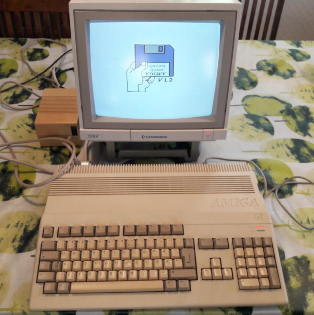 This is in ample evidence over at [Inkoo Vintage Computing], where repairs and upgrades to vintage computers are performed with a nearly religious veneration. Case in point: this detailed blog post about rebuilding a dead Amiga 500 power supply. After receiving the machine as a donation, it was decided to attempt to diagnose and repair the PSU rather than replace it with a newly manufactured one; as much for the challenge as keeping the contemporary hardware in working order.
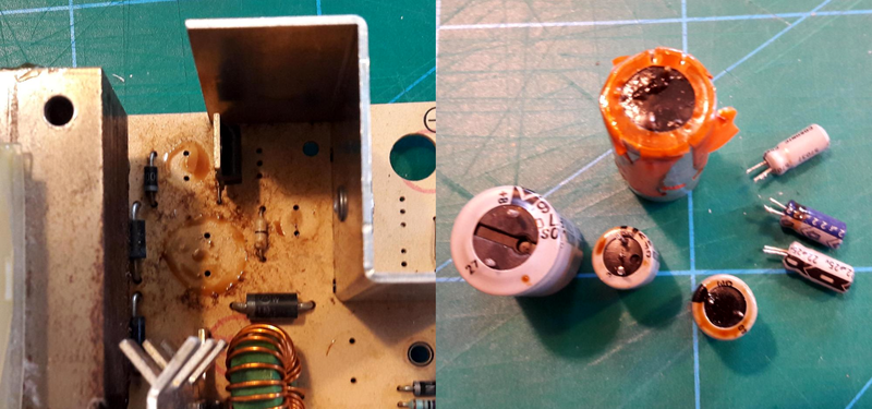
What was found upon opening the PSU probably won’t come as a huge surprise to the average Hackaday reader: bad electrolytic capacitors. But these things weren’t just bulged, a few had blown and splattered electrolyte all over the PCB. After removing the bad caps, the board was thoroughly inspected and cleaned with isopropyl alcohol.
[Inkoo Vintage Computing] explains that there’s some variations in capacitor values between different revisions of the Amiga PSU, so it’s best to match what your own hardware had rather than just trying to look it up online. These capacitors in particular were so old and badly damaged that even reading the values off of them was tricky, but in the end, matching parts were ordered and installed. A new fuse was put in, and upon powering up the recapped PSU, the voltages at the connector were checked to be within spec before being plugged into the Amiga itself.
As a test, the Amiga 500 was loaded up with some demos to really get the system load up. After an hour, the PSU’s transformer was up to 78°C and the capacitors topped out at 60°C. As these parts are rated for 100°C (up from 85°C for the original parts), everything seemed to be within tolerances and the PSU was deemed safe for extended use.
This sort of repair isn’t exactly rare with hardware this old, and we’ve seen similar work done on a vintage Apple power supply in the past. If you’re less concerned with historical accuracy, [Inkoo Vintage Computing] has also shown off adapting an ATX PSU for use with the Amiga.


[Useless comment removed]
[replying to useless comment]
[yet more!]
Regarding the project… it’s good to see her running again. The A500 is a nice machine.
[funny, but honestly still in argumentative mode]
[more defense of the OP]
[yet more defense]
Now, could you maybe get another blog post about fixing an A500 that just produces a green screen ? Need to decide if I try to fix one of these old guys here, or if sell it as-is for parts.
[and finally… this quality comment is the reason we didn’t delete the whole chain]
I worked doing component level repairs on domestic electronics and computers from the days or vinyl records to the days of (80)486. I continued after that till this day but not as my mainstream work so I will offer some tips because it has become an old art now.
Electrolytic capacitors have an internal resistance and therefore generate heat. As time has gone on capacitors became much smaller and as a result they have less surface area to dissipate that heat. Most design engineers still haven’t worked this out. As a consequence capacitors now have a high failure rate especially from poor design where they are close to a heat sink or in a hot environment or both.
The fluid electrolyte dries out. Sometimes you will even see a stain on the PCB from where it has leaked.
Ironically a dry capacitor is more likely to work when it’s heated as the electrolyte becomes more fluid and covers a greater surface area internally so that it has a higher capacitance when hot.
Electrolytics also have a very high tolerance, usually about 20% and a low temperature rating usually 85 degrees Celsius.
For these reasons a capacitance meter is not a good diagnostic tool.
To use a capacitance meter you must first de-solder the cap, heating it and mechanically manipulating it so that it will often give a completely different reading to what it would have given before doing these things.
If you use an Equivalent Series Resistance (ESR) meter then you can test the cap in-circuit and get a much more reliable indication of it’s condition.
The first cap to fail in a switch mode power supply will be the 0.68uF or 1.0uF 50V or 63V capacitor almost every time. Sometimes the series bias resistors on the main switching transistor will over heat and go very high resistance. These are usually hundreds of kOhms by design.
The next to fail will be the output filter caps on the power rails.
If you use an ESR meter then you can find the worst caps and just replace that one or small number and test to see if it works. If it does then you can move on to replacing the other caps that are sub standard.
When replacing them use Low ESR (part number that starts with ESR) caps for the small value caps and use TKR caps for the higher values as low ESR caps are more expensive. Both of these types are rated to 105 degrees Celsius, well above the 85 degrees often seen.
Sadly electrolytic caps are typically place right next to heat source in a PSU because of what they are connected. e.g. right next to a the heat sink of linear regulator or a rectifier diode. These days they also like to jam the smallest package size capacitors into PSU.
The capacitance is determined by the aluminum oxide layer formed on the electrodes, so their value doesn’t change much when they are dried out. The ESR suffers because the electrolyte (i.e. liquid) is part of the conductive path. The higher the ESR goes, the higher the heating effects from the I^2*R losses until the cap fails.
Smaller capacitors have smaller surface area for heat dissipation and holds less liquid, so they are the ones that dries out first.
I have one failed capacitor in a 120V LED driver. It reads 4.3uF 16.36R where as an old cap of the same size reads 4.8uF 1.8R
https://3.bp.blogspot.com/-fCHHecFofHM/W1vMYosYpZI/AAAAAAAAAWY/aQoCgfEpAjEMpqrzeej86rCQIBrUQiW-gCLcBGAs/s320/93411527865905993.JPG
The author here. The guy who donated the Amiga had been googling about Amiga PSUs and ended up in my earlier blog post about building a new PSU for Amiga 500. Apparently he decided that it’s too big investment to build a new one, and didn’t feel comfortable about repairing it, so he donated the machine to me as I was living nearby.
I don’t think his story is unique. This Amiga had been stored in the back of the closet for years, and when his kids got old enough to play with it, he dug it up and let them play the old games for a while – until the PSU gave up. These people are not experts of repairing electronics, but they still would like to keep their old computers running in order to pass their childhood experiences to their kids.
So the reason why I wrote this blog post was to show that it’s not that difficult to replace the capacitors. If somebody else ends up in my blog when googling what to do with their broken PSU, maybe they decide to fix it rather than get rid of the machine. This Amiga 500 found a new home, but more probable destination unfortunately is the e-waste bin.
Maybe Hackaday readers are not the right audience for this blog post, but I decided to submit a tip about it anyway. Getting published on Hackaday makes the article much more visible on Google as well, so it improves the chances that the intended audience will find it. And at least those HaD readers who have read my earlier Amiga-related posts may find this interesting as well.
Also, if you are blogging about vintage computers, and get donated a broken vintage computer because of that, isn’t it kind of expected that you fix the machine and write a blog post about the fix – even if the fix is trivial?
I have two A500 PSUs, one with the transformer and able to supply 2.5A @ 5V and the other one with a switch mode PSU able to supply 4.5A @ 5V. The former one is still running fine after all these years and the caps look good, the latter had 2 rather crispy looking resistors which I replaced with some that are able to sink more power. I checked the caps and all of them are still within the limits for new parts. This PSU is now powering my A1200 with 68030 card.
My opinion after repairing all kinds of old computers… If the caps are leaking, replace them, if not leave them in place as long as everything works.
Just a remark… The A500 uses the -12V internally for 2 things. 1) The RS232 driver chip MC1488 uses -12V and 2) the LF347 Audio amp uses -12V. That means the -12V going too far off course can damage the system.
Thanks for the correction, I removed that sentence from the post.
Feel free to stop reading/commenting anytime, you won’t be missed.
I rebuilt Samsung Galaxy J5 phone once, and HTC Wildfire S wtice. Can I get a post on HaD?
Why not write a blog about it? I’m sure you’re one reader (if you can even manage that) would love to read all about it.
If you can document it thoroughly and educative, sure.
Others did it better already. My “rebuilds” were just a screen replacement for J5 and PCB transplants for Wildfire S. Things as simple as some recapping of PSU. Hell, I did recapping of PSU in my monitor two days ago…
But I can post a link to a video of someone blind, who is fixing his ring-light by soldering some wires. He could use some likes and comments too: https://www.youtube.com/watch?v=UGd2AGZXrEs
Great job! I myself am in search of a vintage, mid to late 80s workstation built by SUN Microsystems when they were running BSD Unix, prior to running Solaris, & long before being bought out by Oracle. My first exposure to SUN Microsystems was in 1987 when I had my first Computer Operator job. Little did I know thirteen years later I’d eventually become a Junior Systems Administrator working with Solaris Unix in a SUN shop running Solaris, & IBM SYS370 running MVS-JES2 environment. Good times back then.
And an error in a first word of the post (On/One)! First ever, congrats!
I have all kinds of working Amiga 500’s, 2000, 2500’s, 3000 and 1200’s and. I’m looking at selling all or some of them and also a CD32 system and I have hundreds of games and I have boxes of backups with games on them but selling as blanks and I also have a couple of monitors.
Where approximately are you located?
78 °C in continuous operation?! I would definitely install a fan nearby, this is a recipe for disaster.
Just a word about electrolytic capacitor temperature ratings. Electrolytics are generally rated at a number of hours life at 85C or 105C. The number of hours are usually between 1000 and 10,000 hours so just looking at the temperature rating is not enough. Also the number of hours life increases rapidly as the temperature goes down. I don’t have the figures in front of me but many electrolytics are rated at 100,000 hours or more at 25C. So, once you have found capacitors with the value and ESR the application needs, look at the rated hours. Then keep the electrolytics cool. Unfortunately many power supplies cram the components into small spaces with electrolytics next to power dissipating components. This is an issue for me as I am building a lot of IOT devices into my house and I need at least 10 years life (around 80,000 hours) for the individual devices so that I don’t end up spending all my time fixing the system. As consumer systems become more complex, mean time to first failure of the parts becomes critical.