[Edward], creator of the Cave Pearl project, an underwater data logger, needed a way to measure temperature with a microcontroller. Normally, this problem is most easily solved by throwing a temperature sensor on the I2C bus — these sensors are cheap and readily available. This isn’t about connecting a temperature sensor in your Arduino. This build is about using the temperature sensor in your clock.
The ATMega328p, the chip at the heart of all your Arduino Uno clones, has within it a watchdog timer that clicks over at a rate of 110 kHz. This watchdog timer is somewhat sensitive to temperature, and by measuring this temperature sensor you can get some idea of the temperature of the epoxy blob that is a modern microcontroller. The trick is calibrating the watchdog timer, which was done with a homemade ‘calibration box’ in a freezer consisting of two very heavy ceramic pots with a bag of rice between them to add thermal mass (you can’t do this with water because you’re putting it in a freezer and antique crocks are somewhat valuable).
By repeatedly taking the microcontroller through a couple of freeze-thaw cycles, [Edward] was able to calibrate this watchdog timer to a resolution of about 0.0025°C, which is more than enough for just about any sensor application. Discussions of accuracy and precision notwithstanding, it’s pretty good.
This technique measures the temperature of the microcontroller with an accuracy of 0.005°C or better, and it’s using it with just the interrupt timer. That’s not to say this is the only way to measure the temperature of an ATMega; some of these chips have temperature sensors built right into them, and we’ve seen projects that use this before. However, this documented feature that’s clearly in the datasheet seems not to be used by many people.
Thanks [jan] for sending this in.


Nooooo not accuracy! I never said that! I was just demonstrating the method has the potential to deliver high resolution. AND I’m still wrestling with jitter – haven’t had time to work out if that’s fundamental to the WDT’s oscillator, or an artifact of the interrupts/code overhead, or burried in the relationship between the xtal and the WDT. Give me a few days to pit the WDT against the DS3231, and I will know better where the jitter is coming from. …
Argh! there is going to be a storm of grouchy people commenting now and I haven’t even finished the experiment yet…
Nonetheless, this is really cool! Great job and keep it up.
you know its clickbait when the original author has to come in and say something.
The atmega interrupts have something like 1-3 clock cycles of jitter due to variable length instructions. The interrupt won’t trigger until the currently executing instruction completes.
err … umm
The ATmega328p has an inbuilt temperature sensor on one of the multiplexed analog converters. The week point for accuracy is that the UNO has the analog ref tied to Vcc but you can switch analog ref to the internal 1.1Volt reference to measure and then switch everything back.
See the datasheet Fig 23-1 on page 206. It also needs cal before it is usable.
https://i.stack.imgur.com/8kz4k.png
Right, I was wondering how you would even create a 0.005°C accurate temperature. I did develop some professional temperature measurement equipment with 24 bit Analog Devices ADCs, ratiometric measurement and high precision PT1000 sensors and I was happy to get 0.1°C accuracy, calibrated in water where ice cubes were just melting.
Regarding your measurement method, I guess this could drift a lot with aging, or voltage fluctuations, probably you don’t get much better accuracy than 2-3°C. Buy just an external temperature sensor with guaranteed specs for a few cents.
Is it resolution or repeatability of 0,005C or actual traceable agreement to the established physical standards?
https://www.tutelman.com/golf/measure/precision.php – accuracy vs precision vs resolution
If you are measuring against a crystal in the same PCB, you have to factory in the temperature coefficient of the crystal which is a S shaped curve. So unless you account for it, the measurement is a difference between the two.
https://www.4timing.com/techcrystal.htm see under: Frequency-Temperature Characteristics
As long as he’s doing his calibrations with the whole board, the crystal is a non-issue. As others said, aging and voltage variations are the major sources of drifting.
Bravo sir, spoken like a true scientist!
Nice method and analysis. The temp sensor 3 pin devices are simple and cheap but good for 0.5 deg C precision or nearly a full degree in human measure. If you have an ADC pin free and it can also take aref voltage, a resistor and transistor or diode can do nicely too. The PN junction voltage drop has a temperature dependence. But this method of using frequency is traditionally the way to get high counts and good data.
Tip: “have equilibrated” = reach equilibrium (if equilibrated is a word). Also consider “are the same temperature”. And never discount the effectiveness of the lowly Styrofoam cup.
I often just use a 1n914 or 1n4148
I built a solar water heater controller 25 (?) years ago and being cheap and lazy I used diodes for temp sensors to make a differential thermostat. The sensitivity is low, so I just used 5 in series. Still using the same diodes and a LM339, no arduinos in the good ole days.
This is an interesting idea. I would be weary of the long term accuracy as RC circuits are known to drift. You are taking advantage of the fact that the largest source of this drift is temperature. There are still other factors, the long term drift of the component values themselves being the big one. Also consider that your sensor is the same die as the rest of the microcontroller.
I would be very careful to make sure my readings were made consistently in the software. Do the exact same thing for at least several seconds before each reading. Things you may not normally think of as being problematic such as illuminating a 7 segment display would be a bad idea. First of all, they cause a lot of power to be dissipated in the chip, which will warm the die. Even if the drive levels are within what the chip spec says is OK per pin and over all. You have to remember that you are doing something totally non standard, and not supported so you need to bend your design and your expectations around that. A 7 segment display is especially troubling because the number of illuminated segments can change. So something as simple as reading out the temperature on a display will actually change the chip dissipation.
Another thing to be concerned about is if the processor ever goes into it’s low power sleep mode. You want to make sure that any readings you take are times to be consistent with the chip waking up as the chips dissipation will change quite a bit going from drawing picowatts to miliwatts. There are also issues with any other parts nearby the micro, including the batteries.
For a change I am not thinking this is a downright terrible idea. I think it has merit, but I think the numbers you are turfing out for the accuracy are extremely optimistic. I would like to see it go through a few hundred thermal cycles and see how repeatable it still is. And I would be very careful in how it is applied. I think it would be very easy to ruin what accuracy you have managed to coddle out of it. If getting a temp measurement this accurate was this easy, there would be a lot more ultra accurate temperature transducers kicking around on the market.
> So something as simple as reading out the temperature on a display will actually change the chip dissipation.
It reminds me Heisenberg’s Uncertainty principle ! (for a totally different kind of reading of course !), but the analogy was there :-)
Ntc sensor?
I doubt the WDT temperature measuring alone is repeatable. It also greatly depends on supply voltage. And possibly other variables. But ATMega has quite precise but poorly calibrated temp sensor with resolution about 1°C. After calibration it may be used as the main temp sensor with the “watchdog thermometer” used to increase the resolution between steps. Why to do this is another question. From my experiments there is no single “true temperature”. In a room there is often several °C difference between different locations. When I was calibrating the ATMega in our freezer I used 3 DS18B20 sensors as reference. Despite being on the same solderless breadboard there was considerable difference between the sensors. It was position dependent – I tested it by swapping them. Also the temperature reported by the ATMega had noticeable lag behind the sensors.
This seems to me more like a way to measure the temperature of the chip itself rather than the temperature of the surrounding area. Granted, a microcontroller is not normally “hot to the touch” but does it not produce at least some significant amount of heat? I would imagine it would be more useful as a way for an Arduino overclocker (is that a thing) to control a fan than anything else. Or I guess it could be a way to detect some kinds of faults. The micro is getting hot. That should not happen. Log a fault and shut down for protection.
Yes, I know. You could try to measure and calibrate for the micro’s normal heat production. That might be ok so long as your micro is pretty much always running the same loop with the same load. (which I must admit is probably not uncommon). Still, I wouldn’t want to try for too much resolution in such a setup as I think the extra decimals would just be measuring variations in the processing load. With external sensors so cheap and their libraries so easy to use it’s hard to justify bothering with that.
Were you around in the Rat Shack days? Did you ever buy a semiconductor “variety” pack? If so then you probably already have a several lifetimes supply of 1n4148 diodes. (and some for your friends too!) Just use those and mount them with the leads long to keep it extended away from the other heat-producing circuitry.
I’ve used a FLIR with a ZnSe macro lens to take pictures of an atmel328. You can see hot spots through the epoxy packaging as the chip does math-intensive stuff. I didn’t have time to do this, but my intent was to see if I could localize die heating during different tasks (i/o, adc, pwm, math, memory transfers) without decapping. Or maybe mill it down until I touched the first bondwire and see how it looked then.
I’d be more concerned about the sensor responding to locally generated heat rather than the true ambient temperature.
Having built a few products with on-board temperature sensors, I can tell you that they’re much better at telling you the temperature of the PCB ground plane than they are about telling you the ambient air temperature :-) Even the data sheets aren’t much help. Get the sensor into the airflow, and make sure there’s no heat generators nearby on the PCB or upstream of the device.
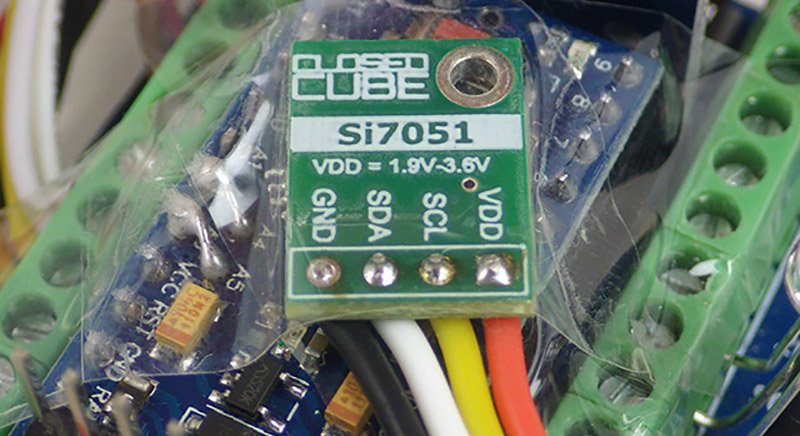
It’s definitively a hack, but if you need a precise sensor without calibration just throw in a Si7051 like pictured. It’s a great chip, tolerance is +-0,15° or something and easy to use and quite cheap. The problem is this thing is tiny (and QFN) and needs 3,3V.
Now *this* is a hack! Creative, useful, and a little shoddy, I love it.
I vaguely recall another hack using the WDT for something “unorthodox”… Quite clever, as I recall, much like this one. Mighta been worthy of linking it, here
Being a benchoff post, am not at all surprised by the utter pedantry of the commentary, sorry, yes, even tongue-in-cheek it gets downright old. What’re y’all, just ‘bots? Eliza held better conversations.
Can I just throw this out there: “duh” and then y’all leave it alone and instead recognize the clever *HACK*, here, which Y’all so otherwise regularly lament so many *Hack*-a-day bloggings’ being “not a hack”?
Jesus, I’m getting tired of y’all.
It’s like none a y’all give a flying rat’s a** about what this site was supposed to be about.
Is there a decent place to look for clever [mis/re/ab]-use of electronics?
I kinda vaguely recall that being called “hacking” and kinda vaguely recall some, actually a large number of, folk ’round here actually giving a da** about the term’s being misappropriated by the media and society-at-large.
But, frankly, with commentary like this crap, y’all seem like shills *trying* to perpetuate those misperceptions.
I’m *really* tiring of you.
Better none than twenty folk stating the glaring obvious.
—
Dude, this is clever. Keep it up, but not for the sake of getting recognition. Here, at least.
F’n eternal september *everywhere* in life, it seems. The New Ring Of He11.