Read Home Power Meters With RTL-SDR

[k-roy] hates electricity. Especially the kind that can be lethal if you’re not careful. Annoyed by the constant advertisements for the popular Sense Home Energy monitors (which must be installed in the main breaker box by an electrician), [k-roy] set out to find a cheaper and easier way. He wondered how the power company monitored his meter, and guessed correctly that it must be transmitting the information wirelessly. Maybe he could just listen in?

Using a cheap RTL-SDR, it didn’t take long for [k-roy] to tap into this transmission and stumbled across the power readings for his entire neighborhood using a simple command:

~/gocode/bin/rtlamr -msgtype=idm --format=json -msgtype=scm+

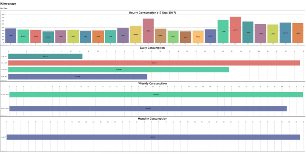
Ironically, the hardest part wasn’t snooping on everyone’s power and water usage patterns in the neighborhood, it was trying to figure out which meter was his. In the end, he was able to make some nice graphical layouts of the data with PHP.

We’ve seen some righteous power meter hacks in our time, but this one stands out for its simplicity and elegance. Be sure to check out [k-roy’s] blog for more details, and [rtlamr’s] github for the program used to read the meters.

Thanks to [Jasper J] for the tip!

Hackaday Prize Entry: An Optical Power Meter

This is the type of crowd that’s famous for building their own test equipment. If you need a way to program a flash chip, don’t go out and buy one — you can just build one. Need a spectrum analyzer? You can build that out of copper clad board. For his Hackaday Prize entry, [oakkar7] is building an optical power meter, capable enough to do futzy fiber work, but still completely DIY.

When you get into networking and telecom connections that don’t begin with the letters ‘RJ’, you start to stumble upon SPF transceivers. These ‘small form factor pluggable’ devices are little modular transceivers capable of handling fiber, Gigabit Ethernet, and other slightly weirder bit pipes. When used with fiber, they can measure optical power in dBm and watts, and can be debugged by a UART.

[oakkar]’s optical power meter uses these SPF transceivers, tied together with a fairly simple circuit consisting of an Arduino, a few tact switches, a Nokia LCD, and an FTDI UART. The key in tying all of this together is an Arduino library for SPF and DDM (Digital Diagnostics Monitoring), giving the user access to all the configuration bits in these transceivers.

While the circuit is simple enough to be built on a piece of perfboard, [oakkar] really knocked it out of the park with the enclosure on this one. With just a little bit of laser cut acrylic and a few standoffs, [oakkar] has a device that actually looks professional, and has most of the capabilities of fancier, more expensive tools.

Hackaday Prize Entry: Smart USB Hub And IoT Power Meter

[Aleksejs Mirnijs] needed a tool to accurately measure the power consumption of his Raspberry Pi and Arduino projects, which is an important parameter for dimensioning adequate power supplies and battery packs. Since most SBC projects require a USB hub anyway, he designed a smart, WiFi-enabled 4-port USB hub that is also a power meter – his entry for this year’s Hackaday Prize.

[Aleksejs’s] design is based on the FE1.1s 4-port USB 2.0 hub controller, with two additional ports for charging. Each port features an LT6106 current sensor and a power MOSFET to individually switch devices on and off as required. An Atmega32L monitors the bus voltage and current draw, switches the ports and talks to an ESP8266 module for WiFi connectivity. The supercharged hub also features a display, which lets you read the measured current and power consumption at a glance.

Unlike most cheap hubs out there, [Aleksejs’s] hub has a properly designed power path. If an external power supply is present, an onboard buck converter actively regulates the bus voltage while a power path controller safely disconnects the host’s power line. Although the first prototype is are already up and running, this project is still under heavy development. We’re curious to see the announced updates, which include a 2.2″ touchscreen and a 3D-printable enclosure.

Put A Reverse Engineered Power Meter In Your Toolkit

It seems that one can buy cheap power meters online and, well, that’s it. They work just fine, but to use them for anything else (like datalogging or control or…) they need a bit more work. The good news is that [Thomas Scherrer], alias [OZ2CPU], just did that reverse engineering work for us.

Inside these budget power meters, you’ll find an LCD driver, a power-monitoring chip, and an STM32F030, which is a low-cost ARM Cortex M0 chip that’s fun to play with on its own. [Thomas] traced out the SPI lines that the power-monitoring chip uses to talk to the microcontroller and broke in to snoop on the signals. Once he got an understanding of all the data, tossing an ATmega88 chip on the SPI line lets him exfiltrate it over a convenient asynchronous serial interface.

If you’re going to do this hack yourself, you should note that the internals of the power meter run at line voltage — the 3.3 V that powers the microcontroller floats on top of the 230 V coming out of [Thomas]’s wall plug. He took the necessary precautions with an isolation transformer while testing the device, and didn’t get shocked. That means that to get the serial data out, you’ll need to use optoisolation (or radio!) on the serial lines.

Now that we know how this thing works on the inside, it’s open-season for power-management hacks. Toss a mains socket and an ESP8266 in a box and you’ve got a WiFi-logging power meter that you can use anywhere, all for under $20. Sweet.

Bike Power Meter With Crank-mounted WiFi Strain Gauges

In any motorsport, the more you know about how the engine is performing, the better a driver is likely to do in a race. That holds for bicycles, too, where the driver just happens to also be the engine. There are plenty of cheap bike computers on the market, but the high-end meters that measure power output are a bit pricey. [chiprobot] is looking to change that with a home-brew, low-cost bike power meter.

The project still appears to be in the proof-of-concept phase, but it’s an interesting concept for sure. The stock crank arms are carefully fitted with two pairs of tiny strain gauges. The gauges are wired in a Wheatstone bridge arrangement, with one gauge in each pair mounted perpendicular to the force on the crank to serve as a static reference. Output from the bridge is fed to an HX711 instrumentation amplifier. The demo video below shows how sensitive the bridge and 24-bit amp are.

The goal is to send crank data to a handlebar-mounted UI via WiFi with a pair of ESP8266 modules. We like the idea of a bicycle area network, but [chiprobot] has his work cut out for him in terms of ruggedizing and weatherproofing all this gear. We’ll be sure to keep an eye on this project. In the meantime, there’s plenty to learn from this bike power meter project we covered last year.

Continue reading “Bike Power Meter With Crank-mounted WiFi Strain Gauges”

Finally, A Power Meter Without Nixies

We’ve had quite a spate of home-brew energy meters on the tip line these days, and that probably reflects a deep inner desire that hackers seem to have to quantify their worlds. Functionally, these meters have all differed, but we’ve noticed a distinct stylistic trend toward the “Nixies and wood” look. Ironically, it is refreshing to see an energy meter with nothing but a spartan web interface for a change.

Clearly, [Tomasz Salwach] had raw data in mind as a design goal, and his Raspberry Pi-based meter delivers. After harvesting current sensing transformers from a bucket of defunct power meter PC boards, [Tomasz] calibrated them with a DIY oscilloscope and wired them and the voltage sensors up to an STM32 Nucleo development board. Data from the MCU goes to the Pi for processing and display as snazzy charts and GUI elements served internally. [Tomasz] was kind enough to include a link to his meter in his tip line post, but asked that we not share it publicly lest HaD readers love the Pi to death. But we can assure you that it works, and it’s kind of fun to peek in on the power usage of a house in Poland in real time.

It’s a nice project that does exactly what it set out to do. But if you missed the recent spate of Nixie-based displays, check out this front hallway meter or this one for a solar-power company CEO’s desk.

Nixie Tubes Adorn Steampunk Solar Power Meter

The appeal of adding Nixie tube displays to a project seems to know no end. First it was Nixie clocks, now it’s Nixie power meters, with the latest addition being this Nixie-Steampunk hybrid solar power monitor.

We’re suckers for a project with a vintage look, and this one pushes all the buttons. Built on commission for a solar power company CEO’s office, [Paul Parry]’s build is based on a Depression-era Metropolitan-Vickers combined voltmeter and ammeter. The huge meters with mirrored scales and the rich wood of the case – our guess is that it’s mahogany – made a great starting point, and after some careful hole drilling, nine IN-18 Nixies were sprouting from the case. A strip of RGB LEDs below decks added the requisite backlighting of the envelopes, and a Raspberry Pi was enlisted to interpret data from the company’s solar farm and drive the tubes and the meters. The project was capped off with a new finish on the case and a couple of fancy brass plaques.

[Paul] sent us the tip for his build after seeing the last power meter we covered, and we have to say they’re both great looking and functional projects. Keep the Nixie projects coming!