Arduino garage door opener

Arduino Garage Door Opener Is Security Minded

Do it yourself garage door openers must be all the rage nowadays. We just got word of another take on this popular idea. [Giles] was commissioned by his friend to find a way to control the friend’s garage door using a smart phone. The request was understandable, considering the costly garage door remote and the fact that the buttons on the expensive remote tended to fail after a while. The inspiration for this project came from some YouTube videos of other similar projects. Those projects all paired an Arduino with a Bluetooth headset in order to control the door from a mobile phone. [Giles] understood that while this would get the job done, it wouldn’t be very secure. Bluetooth headsets typically connect to mobile phones using a four digit PIN. Many of them have known default PINs and even if the default is changed, it wouldn’t take very long to guess a four digit PIN. [Giles] knew he had to find a more secure way.

Continue reading “Arduino Garage Door Opener Is Security Minded”

Upgrade Your Garage Door With Arduino And RFID

RFID Garage Door Opener

[Jason] really wanted to build an RFID controlled garage door opener and decided to turn to Arduino to get the job done. For someone who’s never worked with an Arduino before, he really seemed to know what he was doing.

The Arduino acts as the brains of the operation while an off-the-shelf NFC/RFID reader module is used to read the RFID tags. To add new keys to the system, [Jason] simply swipes his “master” RFID key. An indicator LED lights up and a piezo speaker beeps, letting you know that the system is ready to read a new key. Once the new key is read, the address is stored on an EEPROM. From that point forward the new key is permitted to activate the system.

Whenever a valid key is swiped, the Arduino triggers a relay which can then be used to control just about anything. In this case, [Jason] plans to use it to control his garage door. The system also has a few manual controls. First is the reset button. If this button is held down for two seconds, all of the keys from the EEPROM are erased. This button would obviously only be available to people who are already inside the garage. There is also a DIP switch that allows the user to select how long the relay circuit should remain open. This is configurable in increments of 100ms.

For now the circuit is wired up on a couple of breadboards, but it might be a good idea to use something more permanent. [Jason] could always take it a step further and learn to etch his own PCB’s. Or he could even design a board in Eagle CAD and order a real printed board. Don’t miss the video description of the RFID system below. Continue reading “Upgrade Your Garage Door With Arduino And RFID”

Smartphone Operated Garage Door Is Beginning Of Arduino Home Automation System

[Tim] is showing off the first step in his home automation projected with this smart-phone garage door interface. In the video after the break you can see him open and close the garage door with the touch of a button. There’s also an open or closed indicator that he can check when away from home.

An Arduino takes care of a portion of the control for this project. Like the post we saw yesterday, he’s using PHP code on a webpage to manipulate the Arduino via its USB connection in order to open and close the door using a relay. The door status is also monitored by the Arduino and sent to the PC over the serial connection. The computer uses a Python script to monitor the incoming data and update a text file which is merged into the web interface using a PHP include. Future plans for the system include adding control for heating and air conditioning systems.

If you’re looking to do something like this but wirelessly here’s some advice on ditching the Arduino and using an XBee module instead.

Continue reading “Smartphone Operated Garage Door Is Beginning Of Arduino Home Automation System”

Garage Monitor Has An Extra Arduino

[Jody] wanted to know when his garage door was open. He details his setup which uses a temperature sensor read by an Arduino to send over XBee radio to a computer running a Windows Service. We have seen this twice before, and is noteworthy as a lesson. The XBee radios have the ability to read analog data, relay digital signals, and a lot more. This means the Arduino is completely unnecessary. For example, the Tweet-a-Watt uses two of an XBee’s ADCs to measure voltage and current in a Kill-a-Watt power meter. Programming an XBee is really simple, with the help of tutorials from SparkFun and Adafruit. A bit of programming and soldering should get [Jody] back his Arduino. We hope this note will help you find more creative uses of XBees without microcontrollers.

[Via Make]

Decoding 433 MHz Signals With Arduino & Raspberry Pi

433 MHz radio signals are all around us. They’re used for things like smart power plugs, garage door openers, and home weather stations. Decoding these signals can allow you to interface and work with these devices on your own terms. To help in those efforts, [Joonas Pihlajamaa] has written a three-part tutorial on decoding these signals.

A soundcard makes for a very cheap oscilloscope.

The focus of the tutorials is decoding the signals of a Nexa radio-controlled smart plug. [Joonas] first explores using an Arduino to do the job, paired with a RFM210LCF-433D radio receiver module. This setup dumps out data to a computer over serial for decoding. [Joonas] then tried an alternative strategy, using a soundcard as a “poor man’s oscilloscope” to do the same job, using the same radio module and using Audacity for signal analysis. Finally, [Joonas] brought out the big guns, hooking up a Picoscope digital oscilloscope to a Raspberry Pi 4 for a more deluxe attempt at decoding the signals.

The tutorial goes to show that higher-end tools can make such a job much easier. However, the cheaper techniques are a great way of showing what can be done with the bare minimum in tools. We’re hoping for an exciting fourth part to [Joonas’s] work, where he instructs us on how to decode 433 MHz signals by drinking huge amounts of caffeine and staring at a very fast blinking LED. If you’ve got your own nifty signal analysis (or SIGINT!) hacks, be a good sport and drop them into the tipsline!


Garage Door Controller Gets The IoT Treatment

[TheStaticTurtle] built a custom controller for automating his garage doors. He wanted to retain the original physical button and RF remote control interfaces while adding a more modern wireless control accessible from his internet connected devices. Upgrading an old system is often a convoluted process of trial and error, and he had to discard a couple of prototype versions which didn’t pan out as planned. But luckily, the third time was the charm.

The original door-closer logic was pretty straightforward. Press a button and the door moves. If it’s not going in the desired direction, press the button once again to stop the motor, and then press it a third time to reverse direction. With help from the user manual diagrams and a bit of reverse-engineering, he was able to get a handle on how to plan out his add-on controller to interface with the old system.

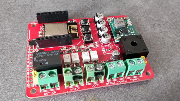
There are many micro-controller options available these days when you want to add IoT to a project, but [TheStaticTurtle] decided to use the old faithful ESP8266 as the brains of his new controller. For his add-on board to work, he needed to detect the direction in which the motor was turning, and detect the limit switches when the door reached end of travel in either direction. Finally, he needed a relay contact in parallel with the activation button to send commands remotely.

To sense if the motor was moving in the “open” or “close” direction, he used a pair of back-to-back opto-couplers in parallel with the motor terminals. He connected another pair of opto-couplers across the two end-limit switches which indicated when the door was fully open or closed, and shut off the motor supply. Finally, a GPIO from the ESP8266 actuates a relay to send the door open and close commands. The boards were designed in EasyEDA and with a quick turnaround from China, he was able to assemble, test and debug his boards pretty quickly.

The code was written using the Arduino IDE and connects the ESP8266 to the MQTT server running on his home automation computer. The end result is a nice dashboard with three icons for open, close and stop, accessible from all the devices connected to his home network. A 3D printed enclosure attaches outside the original control box to keep things tidy. Using hot melt glue as light pipes for the status LED’s is a pretty nifty hack. If you are interested in taking a deeper look at the project, [TheStaticTurtle] has posted all resources on his Github repository.

Arduino Tachometer Clock Fires On All Cylinders

We’re certainly no strangers to unique timepieces around these parts. For whatever reason, hackers are obsessed with finding new and interesting ways of displaying the time. Not that we’re complaining, of course. We’re just as excited to see the things as they are to build them. With the assumption that you’re just as enamored with these oddball chronometers as we are, we present to you this fantastic digital tachometer clock created by [mrbigbusiness].

The multi-function digital gauge itself is an aftermarket unit which [mrbigbusiness] says you can get online for as little as $20 from some sites. All he needed to do was figure out how to get his Arduino to talk to it, and come up with some interesting way to hold it at an appropriate viewing angle. The mass of wires coming out of the back of the gauge might look intimidating, but thanks to his well documented code it shouldn’t be too hard to follow in his footsteps if you were so inclined.

Hours are represented by the analog portion of the gauge, and the minutes shown digitally were the speed would normally be displayed. This allows for a very cool blending of the classic look of an analog clock with the accuracy of digital. He’s even got it set up so the fuel indicator will fill up as the current minute progresses. The code also explains how to use things like the gear and high beam indicators, so there’s a lot of room for customization and interesting data visualizations. For instance, it would be easy to scrap the whole clock idea and use this gauge as a system monitor with some modifications to the code [mrbigbusiness] has provided.

The gauge is mounted to a small project box with some 3D printed brackets and bits of metal rod, complete with a small section of flexible loom to cover up all the wires. Overall it looks very slick and futuristic without abandoning its obvious automotive roots. Inside the base [mrbigbusiness] has an Arduino Nano, a DS1307 RTC connected via I2C, a voltage regulator, and a push button to set the time. It’s a perfectly reasonable layout, though we wonder if it couldn’t be simplified by using an ESP8266 and pulling the time down with NTP.

We’ve seen gauges turned into a timepiece before, but we have to admit that this is probably the most practical realization we’ve seen of the idea yet. Of course if you want to outfit the garage with something a bit more authentic, you can always repurpose a Porsche brake rotor.