PCB of the antenna about to be modded, with components desoldered and different parts of the circuit highlighted

Make A GPS Antenna Compatible With Same Manufacturer’s Receiver

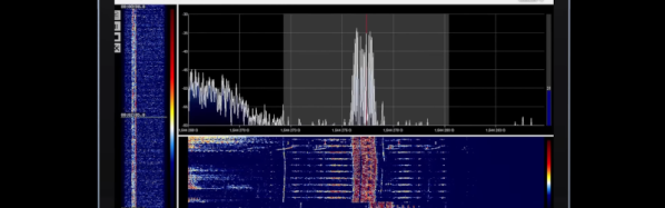
GPS can be a bit complex of a technology – you have to receive a signal below the noise floor, do quite a bit of math that relies on the theory of relativity, and, adding insult to injury, you also have to go outside to test it. Have you ever wondered how GPS antennas work? In particular, how do active GPS antennas get power down the same wire that they use to send signal to the receiver? Wonder not, because [Tom Verbeure] gifts us a post detailing a mod letting a fancy active GPS antenna use a higher-than-expected input voltage.

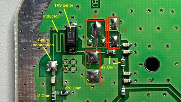
[Tom]’s post has the perfect amount of detail – enough pictures to illustrate the entire journey, and explanations to go with all of it. The specific task is modifying a Symmetricom antenna to work with a Symmetricom GPS receiver, which has a puzzling attribute of supplying 12V to the antenna instead of more common 3.3V or 5V. There’s a few possible options detailed, and [Tom] goes for the cleanest possible one – replacing the voltage regulator used inside of the antenna.

With a suitable replacement regulator installed and a protection diode replaced, the antenna no longer registers as a short circuit, and gets [Tom] a fix – you, in turn, get a stellar primer on how exactly active GPS antennas work. If your device isn’t ready to use active GPS antennas, [Tom]’s post will help you understand another GPS antenna hack we covered recently – modifying the Starlink dish to use an active antenna to avoid jamming on the frontlines.

A bias tee module added inside the Starlink terminal, connected to the pads where a GPS antenna used to be wired

GPS Antenna Mods Make Starlink Terminal Immune To Jammers

The Starlink receivers need positioning and precise timing information to function, and currently the best way to get that information is to use a global navigation satellite system (GNSS) such as GPS. Unfortunately, the antenna used for this secondary satellite connection leaves something to be desired. Of course, when it comes to solving Starlink problems, there’s no one best than [Oleg Kutkov], whose duty is to fix and improve upon Starlink terminals used in Ukraine — and when the specific problem is GPS bands getting jammed by the invading military, you better believe that a fix is due.

[Oleg] sets the scene, walking us through the evolution of GPS circuitry on the Starlink terminals. Then he shows us the simplest mods you can do, like soldering an improved passive antenna in place of the chip antenna currently being used. Then, he takes it up a notch, and shows us how you could attach an active antenna by using a bias tee module, a mod that would surely work wonders on more than just this device! Then, he brings out the test result tables — and the differences are impressive, in that the Starlink terminals with active antenna mods were able to get GPS signal in areas with active jamming going on, while the unmodified ones could not.

The post is exceptionally accessible, and a must read for anyone wondering about GPS antenna reception problems in customer-accessible devices. This is not the only Starlink hardware mod we’ve seen [Oleg] make, we’ve just covered his Starlink Ethernet port restoration journey that meticulously fixes Ethernet connectivity oversights in the newer models, and the blog also has an article about powering Starlink terminals without the need for PoE, so, do check it out if you’re looking for more!

A Homebrew GPS Correction System For DIY Land Surveying

For those of you rushing to the comment section after reading the title to tell [Ben Dauphinee] that his DIY land surveying efforts are for naught because only a licensed surveyor can create a legally binding property description, relax — he already knows. But what he learned about centimeter-resolution GPS is pretty interesting, especially for owners of large rural properties like him.

[Ben]’s mapping needs are less rigorous than an official survey; he just wants to get the locations of features like streams and wood lines, and to get topographic elevations so that he has a general “lay of the land” for planning purposes. He originally engaged a surveyor for that job, but after shelling out $4,600 to locate a single property line, he decided to see what else could be done. Luckily, real-time kinematics, or RTK, holds the key. RTK uses a fixed GPS station to provide correction signals to a mobile receiver, called a rover. If the fixed station’s position is referenced to some monument of known position, the rover’s position can be placed on a map to within a couple of centimeters.

To build his own RTK system, [Ben] used some modules from SparkFun. The fixed station has an RTK breakout board and a multi-band GNSS antenna to receive positioning data, along with a Raspberry Pi to run the RTK server. An old iPhone with a prepaid SIM provides backhaul to connect to the network that provides correction data. [Ben]’s rover setup also came mainly from SparkFun, with an RTK Facet receiver mounted on a photographer’s monopod. Once everything was set up and properly calibrated, he was able to walk his property with the rover and measure locations to within 4 centimeters.

This was not an inexpensive endeavor — all told, [Ben] spent about $2,000 on the setup. That’s a lot, especially on top of what he already paid for the legal survey, but still a fraction of what it would have cost to have a surveyor do it, or to buy actual surveyor’s equipment. The post has a ton of detail that’s worth reading for anyone interested in the process of mapping and GPS augmentation.

Hackaday Podcast Episode 251: Pluto, Pinball, Speedy Surgery, And DIY GPS

Welcome to 2024! This time around, Elliot and Dan ring in a new year of awesome hacks with quite an eclectic mix. We kick things off with a Pluto pity party and find out why the tiny ex-planet deserved what it got. What do you do if you need to rename a bunch of image files? You rope a local large-language model in for the job, of course. We’ll take a look at how pinball machines did their thing before computers came along, take a fractal dive into video feedback, and localize fireworks with a fleet of Raspberry Pi listening stations. Ever wonder what makes a GPS receiver tick? The best way to find out might be to build one from scratch. Looking for some adventure? A ride on an electroluminescent surfboard might do, or perhaps a DIY “Vomit Comet” trip would be more your style. And make sure you stick around for our discussion on attempts to optimize surgery efficiency, and our look back at 2023’s top trends in the hardware world.


Grab a copy for yourself if you want to listen offline.

Continue reading “Hackaday Podcast Episode 251: Pluto, Pinball, Speedy Surgery, And DIY GPS”

Building A GPS Receiver From The Ground Up

One of the more interesting facets of GPS is that, at least from the receiver’s point-of-view, it’s a fairly passive system. All of the information beamed down from the satellites is out in the ether, all the time, free for anyone on the planet to receive and use as they see fit. Of course you need to go out and buy a receiver or, alternatively, possess a certain amount of knowledge to build a circuit that can take those signals and convert them into something usable. Luckily, [leaning_tower] has the required knowledge and demonstrates it with this DIY GPS receiver.

This receiver consists of five separate circuit boards, all performing their own function. The first, a mixer board, receives the signal via an active antenna and converts it to a lower frequency. From there it goes to a second mixer and correlation board to compare the signal to a local reference, then a signal processing board that looks at this intermediate frequency signal to make sense of the data its seeing. Finally, an FPGA interfacing board ties everything together and decodes the information into a usable form.

Dealing with weak signals like this has its own set of challenges, as [leaning_tower] found out. The crystal oscillator had to be decapped and modified to keep from interfering with the GPS radio since they operated on similar frequencies. Even after ironing out all the kinks, the circuit takes a little bit of time to lock on to a specific satellite but with a second GPS unit for checking and a few weeks of troubleshooting, the homebrew receiver is up and running. It’s an impressive and incredibly detailed piece of work which is usually the case with sensitive radio equipment like GPS. Here’s another one built on a Raspberry Pi with 12 channels and a pretty high accuracy.

Designing A PCB GPS Antenna From Scratch

These days, when it comes to GPS devices the antenna is typically part of the package. But what better opportunity for [Pepijn] to learn how to make a GPS antenna from scratch for a badge add-on?

A patch antenna is an antenna of a flat design, which [Pepijn] was going to put directly on a PCB. However, there was added complexity due to GPS being a circularly polarized signal, and that meant doing some research.

Sadly, nowhere did [Pepijn] encounter a straightforward reference design or examples, but in the end success came from going with a truncated corner patch antenna design and using simulation software to figure out exactly what dimensions were needed. (The openEMS free simulation software didn’t bring success, but the non-free Sonnet with a trial license did the trick.) The resulting PCB may not look particularly complex, but every detail matters in such designs.

KiCad handled the PCB CAD design but the prototype came from cutting the PCB on a CNC machine instead of having it fabricated and shipped; a much cheaper and faster option for those with access to the right tools. A bit more testing had the prototype looking good, but the real proof came when it successfully received GPS signals and spewed valid NMEA messages. The design files are on GitHub but as [Pepijn] says, the project was about the journey more than anything else.

The Voice Of GPS

Tuning into a GPS satellite is nothing new. Your phone and your car probably do that multiple times a day. But [dereksgc] has been listening to GPS voice traffic. The traffic originates from COSPAS-SARSAT, which is a decades-old international cooperative of 45 nations and agencies that operates a worldwide search and rescue program. You can watch a video about it below.

Nominally, a person in trouble activates a 406 MHz beacon, and any of the 66 satellites that host COSPAS-SARSAT receivers can pick it up and relay information to the appropriate authorities. These beacons are often attached to aircraft or ships, but there are an increasing number of personal beacons used by campers, hikers, and others who might be in danger and out of reach of a cell phone. The first rescue from this system was in 1982. By 2021, 3,632 people were rescued thanks to the system.

The satellites that listen to the beacon frequencies don’t process the signals. They use a transponder that re-transmits anything it hears on a much higher downlink frequency. These transponders are always payloads on other satellites like navigation or weather satellites. But because the transponder doesn’t care what it hears, it sometimes rebroadcasts signals from things other than beacons. We were unclear if these were rogue radios or radios with spurious emissions in the translator’s input range.

The video has practical tips on how to tune in several of the satellites that carry these transponders. Might be a fun weekend project with a software-defined radio.

We’ve seen homebrew satellite devices, but none for an emergency beacon — we aren’t sure what the legal aspects of that would be. There are other satellites that unknowingly host pirate radio stations, too.

Continue reading “The Voice Of GPS”