DIY 6 GHZ Pulse Compression Radar

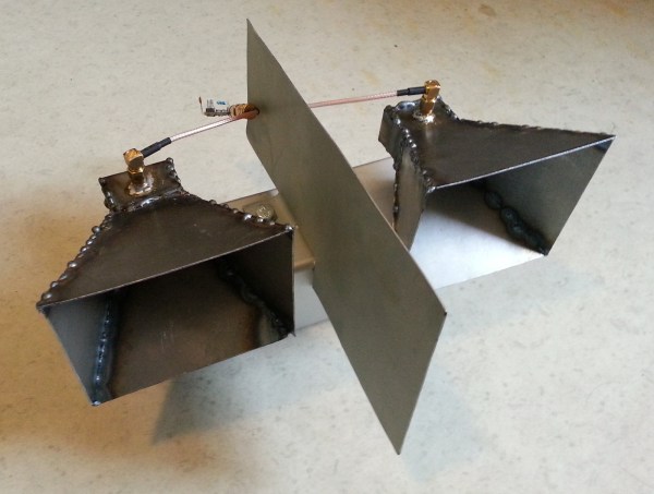
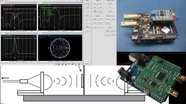
Conceptually, radar is pretty simple: send out a radio wave and time how long it takes to get back via an echo. However, in practice, there are a number of trade-offs to consider. For example, producing a long pulse has more energy and range, but limits how close you can see and also the system’s ability to resolve objects that are close to each other. Pulse compression uses a long transmission that varies in frequency. Reflected waves can be reconstituted to act more like a short pulse since there is information about the exact timing of the reflected energy. [Henrik] didn’t want to make things too easy, so he decided to build a pulse compression radar that operates at 6 GHz.

In all fairness, [Henrik] is no neophyte when it comes to radar. He’s made several more traditional devices using a continuous wave architecture. However, this type of radar is only found in a few restricted applications due to its inherent limitations. The new system can operate in a continuous wave mode, but can also code pulses using arbitrary waveforms.

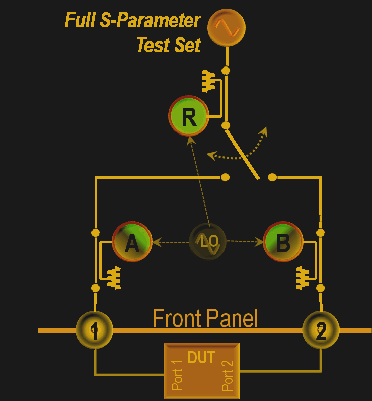
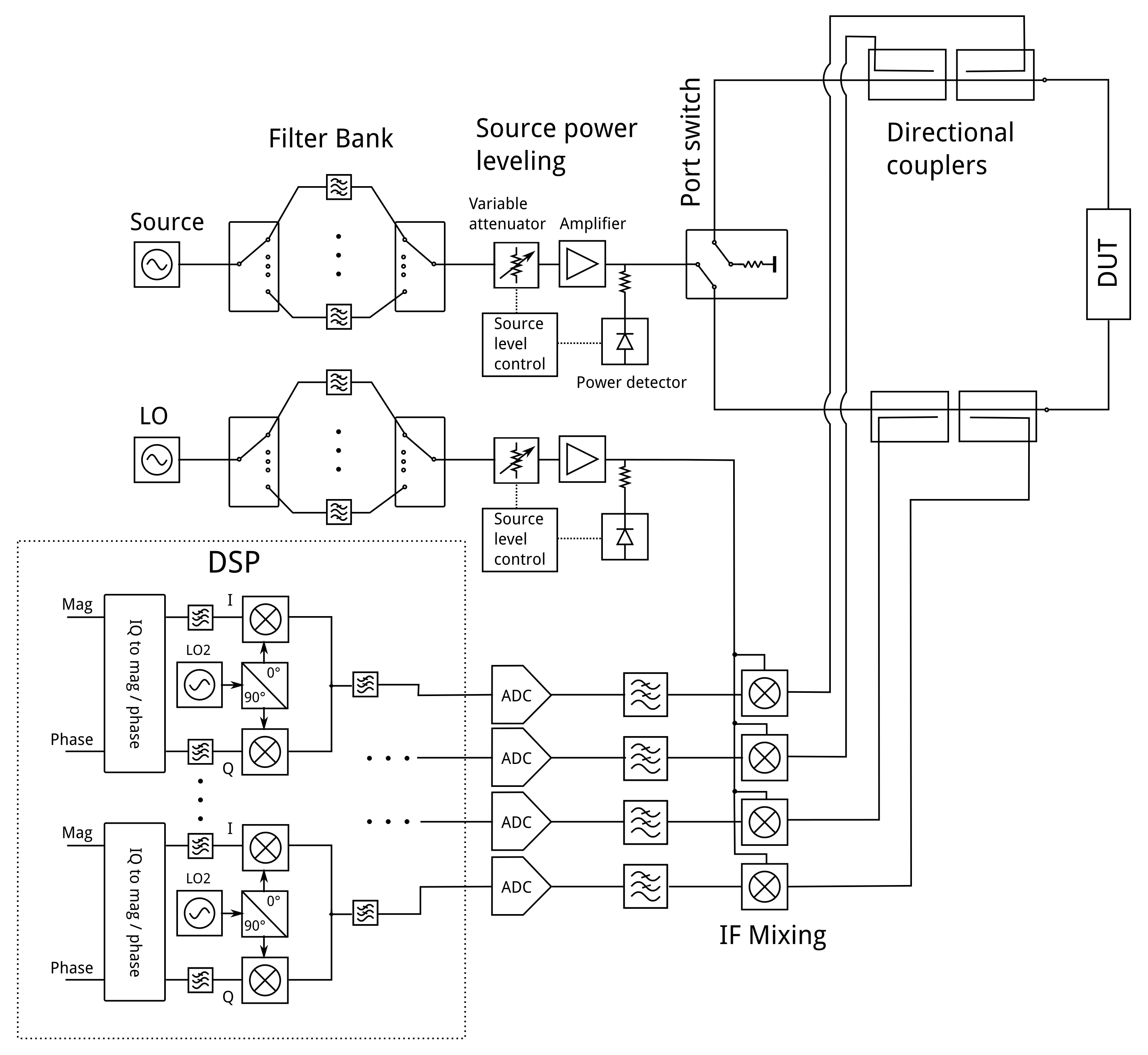
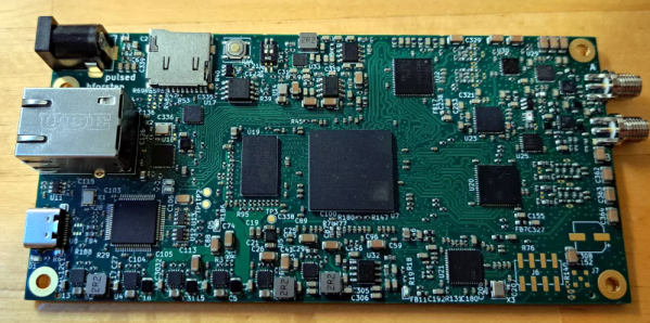
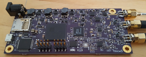
Some design choices were made to save money. For example, the transmitter and receiver have limited filtering. In addition, the receiver isn’t a superheterodyne but more of a direct conversion receiver. The signal processing is made much easier by using a Zynq FPGA with a dual-core ARM CPU onboard. These were expensive from normal sources but could be had from online Chinese vendors for about $17. The system could boot Linux, although that’s future work, according to [Henrik].

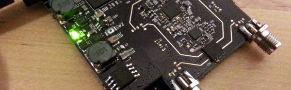
At 6 GHz, everything is harder. Routing the PCB for DDR3 RAM is also tricky, but you can read how it was done in the original post. To say we were impressed with the work would be an understatement. We bet you will be too.

Radar has come a long way since World War II and is in more places than you might guess. We hate to admit it, but we’d be more likely to buy a ready-made radar module if we needed it.

Bike-Mounted Synthetic-Aperture Radar Makes Detailed Images

Synthetic-aperture radar, in which a moving radar is used to simulate a very large antenna and obtain high-resolution images, is typically not the stuff of hobbyists. Nobody told that to [Henrik Forstén], though, and so we’ve got this bicycle-mounted synthetic-aperture radar project to marvel over as a result.

Neither the electronics nor the math involved in making SAR work is trivial, so [Henrik]’s comprehensive write-up is invaluable to understanding what’s going on. First step: build a 6-GHz frequency modulated-continuous wave (FMCW) radar, a project that [Henrik] undertook some time back that really knocked our socks off. His FMCW set is good enough to resolve human-scale objects at about 100 meters.

Moving the radar and capturing data along a path are the next steps and are pretty simple, but figuring out what to do with the data is anything but. [Henrik] goes into great detail about the SAR algorithm he used, called Omega-K, a routine that makes use of the Fast Fourier Transform which he implemented for a GPU using Tensor Flow. We usually see that for neural net applications, but the code turned out remarkably detailed 2D scans of a parking lot he rode through with the bike-mounted radar. [Henrik] added an auto-focus routine as well, and you can clearly see each parked car, light pole, and distant building within range of the radar.

We find it pretty amazing what [Henrik] was able to accomplish with relatively low-budget equipment. Synthetic-aperture radar has a lot of applications, and we’d love to see this refined and developed further.

[via r/electronics]

Homemade 6 GHz Radar, V3

The third version of [Henrik Forstén] 6 GHz frequency-modulated continuous wave (FMCW) radar is online and looks pretty awesome. A FMCW radar is a type of radar that works by transmitting a chirp which frequency changes linearly with time. Simple continuous wave (CW) radar devices without frequency modulation cannot determine target range because they lack the timing mark necessary for accurately time the transmit and receive cycle in order to convert this information to range. Having a transmission signal modulated in frequency allows for the radar to have both a very high accuracy of range and also to measure simultaneously the target range and its relative velocity.

Like the previous versions, [Henrik] designed a four-layer pcb board and used his own reflow oven to solder all the ~350 components. This process, by itself, is a huge accomplishment. The board, much bigger than the previous versions, now include digital signal processing via FPGA.

[Henrik’s] radar odyssey actually started back in 2014, where his first version of the radar was detailed and shared in his blog. A year later he managed to solve some of the issues he had, design a new board with significant improvements and published it again. As the very impressive version three is out, we wonder what version four will look like.

In the video of [Henrik] riding a bicycle in a circle in front of the radar, we can see the static light posts and trees while he, seen as a small blob, roams around:

Continue reading “Homemade 6 GHz Radar, V3”

Network Analysers: The Electrical Kind

Instrumentation has progressed by leaps and bounds in the last few years, however, the fundamental analysis techniques that are the foundation of modern-day equipment remain the same. A network analyzer is an instrument that allows us to characterize RF networks such as filters, mixers, antennas and even new materials for microwave electronics such as ceramic capacitors and resonators in the gigahertz range. In this write-up, I discuss network analyzers in brief and how the DIY movement has helped bring down the cost of such devices. I will also share some existing projects that may help you build your own along with some use cases where a network analyzer may be employed. Let’s dive right in.

Network Analysis Fundamentals

As a conceptual model, think of light hitting a lens and most of it going through but part of it getting reflected back.

The same applies to an electrical/RF network where the RF energy that is launched into the device may be attenuated a bit, transmitted to an extent and some of it reflected back. This analysis gives us an attenuation coefficient and a reflection coefficient which explains the behavior of the device under test (DUT).

Of course, this may not be enough and we may also require information about the phase relationship between the signals. Such instruments are termed Vector Network Analysers and are helpful in measuring the scattering parameters or S-Parameters of a DUT.

The scattering matrix links the incident waves a1, a2 to the outgoing waves b1, b2 according to the following linear equation: \begin{bmatrix} b_1 \\ b_2 \end{bmatrix} = \begin{bmatrix} S_{11} & S_{12} \\ S_{21} & S_{22} \end{bmatrix} * \begin{bmatrix} a_1 \\ a_2 \end{bmatrix} .

The equation shows that the S-parameters are expressed as the matrix S, where and denote the output and input port numbers of the DUT.

This completely characterizes a network for attenuation, reflection as well as insertion loss. S-Parameters are explained more in details in Electromagnetic Field Theory and Transmission Line Theory but suffice to say that these measurements will be used to deduce the properties of the DUT and generate a mathematical model for the same.

General Architecture

As mentioned previously, a simple network analyzer would be a signal generator connected and a spectrum analyzer combined to work together. The signal generator would be configured to output a signal of a known frequency and the spectrum analyzer would be used to detect the signal at the other end. Then the frequency would be changed to another and the process repeats such that the system sweeps a range of frequencies and the output can be tabulated or plotted on a graph. In order to get reflected power, a microwave component such as a magic-T or directional couplers, however, all of this is usually inbuilt into modern-day VNAs.
Continue reading “Network Analysers: The Electrical Kind”

A VNA On A 200 Euro Budget

If you were to ask someone who works with RF a lot and isn’t lucky enough to do it for a commercial entity with deep pockets what their test instrument of desire would be, the chances are their response would mention a vector network analyser. A VNA is an instrument that measures the S-parameters of an RF circuit, that rather useful set of things to know whose maths in those lectures as an electronic engineering student are something of a painful memory for some of us.

The reason your RF engineer respondent won’t have a VNA on their bench already will be fairly straightforward. VNAs are eye-wateringly expensive. Second-hand ones are in the multi-thousands, new ones can require the keys to Fort Knox. All this is no obstacle to [Henrik Forstén] though, he’s built himself a 30MHz to 6 GHz VNA on the cheap, with the astoundingly low budget of 200 Euros.

The operation of a VNA

On paper, the operation of a VNA is surprisingly simple. RF at a known power level is passed through the device under test into a load, and the forward and reverse RF is sampled on both its input and output with a set of directional couplers. Each of the four couplers feeds what amounts to an SDR, and the resulting samples are processed by a computer. His write-up contains a full run-down of each section of the circuit, and is an interesting primer on the operation of a VNA,

[Henrik] admits that his VNA isn’t as accurate an instrument as its commercial cousins, but for his tiny budget the quality of his work is evident in that it is a functional VNA. He could have a batch of these assembled and he’d find a willing queue of buyers even after taking into account the work he’s put in with his pricing.

[Henrik]’s work has appeared on these pages several times before, and every time he has delivered something special. We’ve seen his radar systems, home-made horn antennas, and a very well-executed ARM single board computer. This guy is one to watch.

Thanks [theEngineer] for the tip.

An Improvised Synthetic Aperture Radar

[Henrik] is at it again. Another thoroughly detailed radar project has shown up on his blog. This time [Henrik] is making some significant improvements to his previous homemade radar with the addition of Synthetic Aperture Radar (SAR) to his previous Frequency Modulated Continuous Wave (FMCW) system.

[Henrik’s] new design uses an NXP LPC4320 which uniquely combines an ARM Cortex-M4 MCU along with a Cortex-M0 co-processor. The HackRF also uses this micro as it has some specific features that can be taken advantage of here like the Serial GPIO (SGPIO) which can be tediously configured and high-speed USB all for ~$8 in single quantity. The mixed signal design is done in two boards, a 4 layer RF board and 2 layer digital board.

Like the gentleman he is, [Henrik] has included schematics, board files, and his modified source from the HackRF project in his github repo. There is simply too much information in his post to attempt to summarize here, if you need instant gratification check out the pictures after the break.

The write-up on his personal blog is impressive and worth look if you didn’t catch our coverage of his single board Linux computer, or his previous radar design.

Continue reading “An Improvised Synthetic Aperture Radar”

Horn Antenna

Building A Horn Antenna For Radar

So you’ve built yourself an awesome radar system but it’s not performing as well as you had hoped. You assume this may have something to do with the tin cans you are using for antennas. The obvious next step is to design and build a horn antenna spec’d to work for your radar system. [Henrik] did exactly this as a way to improve upon his frequency modulated continuous wave radar system.

To start out, [Henrik] designed the antenna using CST software, an electromagnetic simulation program intended for this type of work. His final design consists of a horn shape with a 100mm x 85mm aperture and a length of 90mm. The software simulation showed an expected gain of 14.4dB and a beam width of 35 degrees. His old cantennas only had about 6dB with a width of around 100 degrees.

The two-dimensional components of the antenna were all cut from sheet metal. These pieces were then welded together. [Henrik] admits that his precision may be off by as much as 2mm in some cases, which will affect the performance of the antenna. A sheet of metal was also placed between the two horns in order to reduce coupling between the antennas.

[Henrik] tested his new antenna in a local football field. He found that his real life antenna did not perform quite as well as the simulation. He was able to achieve about 10dB gain with a field width of 44 degrees. It’s still a vast improvement over the cantenna design.

If you haven’t given Radar a whirl yet, check out [Greg Charvat’s] words of encouragement and then dive right in!