24-port GPIO On A PCI Card

btgpio

So you’ve got a project running on an x86 board and you’d like some GPIO pins. Whether you want to read a few buttons, light up a few LEDs, put an accelerometer in your computer or whatever, you’ve got a problem. Luckily there’s an easy way to get 24 GPIO pins on an x86 board using a PCI card for just a few bucks.

The key component of the build is a PCI TV Tuner card made by Hauppague under the WinTV brand. If you’ve got one of these cards with either a Brooktree bt848, bt849, bt878 or bt879 video capture chip, having 24 GPIO pins is just a spool of magnet wire, a soldering iron, and a steady hand away.

It’s a great build if you’d like some GPIO action without going through the usual parallel port mess, and especially useful since these WinTV capture cards can be had from the usual Internet suppliers for just a few bucks. You’ll need a driver, of course, but the relevant Linux kernel driver – bt8xxgpio – should be included any reasonably modern distro.

Special thanks to [Dex Hamilton] for notifying us of this build.

Cheap Hack Gets PCI-X Card Working In PCI Slot

PCI and PCI-X are not directly compatible, and you’d be forgiven for thinking that means you’re out of luck if you need to use a PCI-X card in a machine that only has basic PCI slots. And yet, that needn’t be the case. As [Peter] shows us, you can work around this with a cheap hacky hack. Our favorite kind!

[Peter] had a PCI-X RAID card that he wanted to use on his Socket 7-based computer. The 3ware 9550SX PCI-X card is 3.3 V only, and doesn’t fit in a typical PCI slot. It’s not compatible mechanically or electrically. Enter a PCI-X riser, which gets around the missing notch that would normally not let the card sit in the slot. Other than that, it just took masking off some pins to avoid damage from the 5 V rail. Throughput is good, too, reportedly sitting at roughly 60-70 MB/s.

The hard part is probably finding a PCI-X riser; PCI-Express stuff is far more common. Few of us need to deal with PCI-X anymore, but if you’re working on some ancient industrial hardware or something, this hack might just save your beans from the roast pot one day.

Continue reading “Cheap Hack Gets PCI-X Card Working In PCI Slot”

Running A Modern Graphics Card In A 33 MHz PCI Slot

If you ever looked at a PCI to PCIe x16 adapter and wondered what’d happen if you were to stick a modern PCIe GPU in it, the answer apparently is ‘it works’ according to an attempt by [Circuit Rewind]. As long as you accept needing to supply external power with even a low-end GT 1030 card – as the PCI slot cannot provide enough power – and being limited to a single PCIe lane. This latter point isn’t so much of an issue as a single PCIe lane offers more bandwidth than the (shared) PCI bus anyway.

Despite the somewhat improvised setup, the GT 1030 card provided a decent 1080p experience in a range of games, after removing half of the 8 GB of system RAM before the configuration would work, probably due to VRAM mapping issues. Since the mainboard used also offered PCIe, the same card was run in a PCIe x4 slot, as well as in an x1 configuration, both with noticeably higher performance and putting the ‘why’ in ‘try’.

Perhaps unsurprisingly, a RTX 3080 also booted fine with external power and only 4 GB system RAM installed. Despite the PCIe x1 link, the system was able to finish a 3D benchmark and play Doom 2016, but with only 4 GB of system RAM and an old Athlon quad-core CPU, it was a terrible experience. Perhaps the most fascinating lesson to learn from this is that PCI and PCIe are amazingly compatible with only a simple translation bridge, even if high-performance graphics aren’t quite what PCI was meant for. After all, that’s why we got cursed with AGP for many years.

Continue reading “Running A Modern Graphics Card In A 33 MHz PCI Slot”

PCIe For Hackers: Our M.2 Card Is Done

We’ve started designing a PCIe card last week, an adapter from M.2 E-key to E-key, that adds an extra link to the E-key slot it carries – useful for fully utilizing a few rare but fancy E-key cards. By now, the schematic is done, the component placement has been figured out, and we only need to route the differential pairs – should be simple, right? Buckle up.

Getting Diffpairs Done

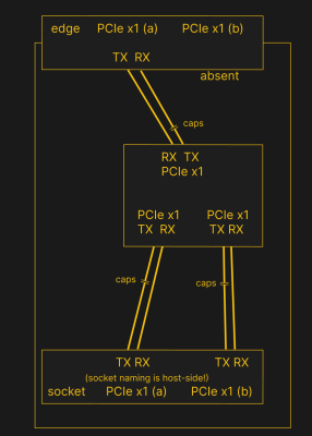
PCIe needs TX pairs connected to RX on another end, like UART – and this is non-negotiable. Connectors will use host-side naming, and vice-versa. As the diagram demonstrates, we connect the socket’s TX to chip’s RX and vice-versa; if we ever get confused, the laptop schematic is there to help us make things clear. To sum up, we only need to flip the names on the link coming to the PCIe switch, since the PCIe switch acts as a device on the card; the two links from the switch go to the E-key socket, and for that socket’s purposes, the PCIe switch acts as a host.

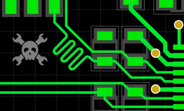
While initially routing this board, I absolutely forgot about one more important thing for PCIe – series capacitors on every data pair, on the host TX side of the link. We need three capacitor pairs here – on TX of the PCIe switch uplink, and two pairs on TX side of the switch – again, naming is host-side. I only remembered this after having finished routing all the diffpairs, and, after a bit of deliberation, I decided that this is my chance to try 0201 capacitors. For that, I took the footprints from [Christoph]‘s wonderful project, called “Effect of moon phase on tombstoning” – with such a name, these footprints have got to be good.

We’ve talked about differential pair calculations before in one of the PCIe articles, and there was a demo video too! That said, let’s repeat the calculations on this one – I’ll show how to get from “PCB fab website information” to “proper width and clearance diffpairs”, with a few fun shortcuts. Our setup is, once again, having signals on outer layers, referenced to the ground layer right below them. I, sadly, don’t yet understand how to calculate differential impedance for signal layers sandwiched between two ground planes, which is to say – if there’s any commenters willing to share this knowledge, I’d appreciate your input tremendously! For now, I don’t see that there’d be a tangible benefit to such an arrangement, anyway.

Continue reading “PCIe For Hackers: Our M.2 Card Is Done”

PCIe For Hackers: An M.2 Card Journey

I’ve designed a few M.2 adapters for my own and my friends’ use, and having found those designs online, people have asked me for custom-made adapters. One of these requests is quite specific – an adapter that adds one more PCIe link to an E-key M.2 slot, the kind of slot you will see used in laptops for WiFi cards.

See, the M.2 specification allows two separate PCIe links connected to the E-key slot; however, no WiFi cards use this apart from some really old WiGig-capable ones, and manufacturers have long given up on connecting a second link. Nevertheless, there are some cards like the Google Coral M.2 E-key dual AI accelerator and the recently announced uSDR, that do indeed require the second link – otherwise, only half of their capacity is available.

It’s not clear why both Google and WaveletSDR designed for a dual-link E-key socket, since those are a rare occurrence; for the Google card, there are plenty of people complaining that the board they bought just doesn’t fully work. In theory, all you need to do to help such a situation, is getting a second PCIe link from somewhere, then wiring it up to the socket – and a perfect way to do it is to get a PCIe switch chip. You will lose out on some bandwidth because the uplink PCIe connection of the switch can only go so fast; for things like this AI accelerator, it’s not much of a problem since the main point is to get the second device accessible. For the aforementioned SDR, it might turn out useless, or you might win some but lose some – can’t know until you try! Continue reading “PCIe For Hackers: An M.2 Card Journey”

Use A Mini PCI-e 3G Card With USB Instead

Back the late 2000s, when netbooks were the latest craze, some models would come with an inbuilt 3G modem for Internet access. At the time, proper mobile Internet was a hip cool thing too — miles ahead of the false prophet known as WAP. These modems would often slot into a Mini PCI-e slot in the netbook motherboard. [delokaver] figured out how to use these 3G cards over USB instead.

It’s actually a fairly straightforward hack. The Mini PCI-e standard has a couple of pins dedicated to USB data lines, which the modem in question uses for communicating with the host computer. Unfortunately it’s not quite as simple as just soldering on a four-wire USB cable. The modem relies on the 3.3V power from the Mini PCI-e slot instead of the 5V from USB. No problem, just get a low-dropout 3.3V regulator and run that off the USB port. Then, it’s a simple enough matter of figuring out which pins are used to talk to the SIM card, and soldering them up to a SIM adapter, or directly to the card itself if you’re so inclined. The guide covers a single model of 3G modem but it’s likely the vast majority of these use a very similar setup, so don’t be afraid to have a go yourself.

Overall Mini PCI-e is a fairly unloved interface, but we’ve seen the reverse of this hack before, a Mini PCI-e to USB adapter used to add a 12-axis sensor to a laptop.

[Thanks to Itay for the tip!]

STM32 Driving A PCIe Video Card

[Gpuhackr] chose his username to explain exactly how he spends his time. For instance, here he’s using an STM32 Discovery board to drive an AMD Radeon HD 2400 graphics card. The ARM microcontroller isn’t actually using the PCIe interface on the card. Instead, [Gpuhackr] has patched into the debugging interface built into the card itself. This isn’t quite as straight forward as it sounds, but if you do the wiring carefully it’s a pretty intersting way to connect an ARM to an LCD monitor.

This project would be almost impossible if it weren’t for the open source code which AMD has released. This lets him implement the card’s 3D rendering features. The demo directly programs the UVD Xtensa CPU which is on the video card. It draws a cube with color gradients on each side. The cube spins while the debug information is overlaid on the screen. In this case the ARM chip/board is really being used as a programmer to upload some custom firmware. But we think a real code-ninja could implement a communications protocol to open up a simple way to drive the card in real-time.

[Thanks uMinded]