Radio Frequency Burns, Flying A Kite, And You

Most hams can tell you that it’s possible to get a nasty RF burn if you accidentally touch an antenna while it’s transmitting. However, you can also cop a nasty surprise on the receiving end if you’re not careful, as explained in a video from [Grants Pass TV Repair].

It’s hard to see in a still image, but the RF burns from the kite antenna actually generate a little puff of smoke on contact.

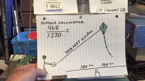
An experiment was used to demonstrate this fact involving a kite and a local AM broadcaster. A simple calculation revealed that an antenna 368 feet and 6 inches long would be resonant with the KAJO Radio signal at 1.270 MHz. At half the signal’s wavelength, an antenna that long would capture plenty of energy from the nearby broadcast antenna.

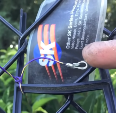
Enter the kite, which served as a skyhook to loft an antenna that long. With the wire in the air picking up a strong signal from the AM radio tower, it was possible to get a noticable RF burn simply by touching the end of the antenna.

The video explains that this is a risky experiment, but not only because of the risk of RF burn itself. It’s also easy to accidentally get a kite tangled in power lines, or to see it struck by lightning, both of which would create far greater injuries than the mild RF burn seen in the video. In any case, even if you know what you’re doing, you have to be careful when you’re going out of your way to do something dangerous in the first place.

AM radio towers aren’t to be messed with; they’ve got big power flowing. Video after the break.

Continue reading “Radio Frequency Burns, Flying A Kite, And You”

AM Radio Broadcast Uses Phasor To Let Eight Towers Spray One Big Signal

If you’re in the commercial AM radio business, you want to send your signal as far and wide as possible. More listeners means you can make more ad revenue, after all. [Jeff Geerling] recently visited a tower site for WSDZ-AM, which uses a full eight towers to broadcast its 20kW AM signal. To do that, it needs a phasor to keep everything in tune. Or, uh… phase.

The phasor uses a bunch of variable inductors and capacitors to manage the phase of the signal fed to each tower. Basically, by varying the phase of the AM signal going to each of the 8 transmitter towers, it’s possible to tune the directionality of the tower array. This allows the station to ensure it’s only broadcasting to the area it’s legally licensed to do so.

The tower array is also configured to broadcast slightly differently during the day and at night to account for the differences in propagation that occur. A certain subset of the 8 towers are used for the day propagation pattern, while a different subset is used to shape the pattern for the night shift. AM signals can go far farther at night, so it’s important for stations to vary their output to avoid swamping neighbouring stations when the sun goes down.

[Jeff’s] video is a great tour of a working AM broadcast transmitter. If you’ve ever wondered about the hardware running your local commercial station, this is the insight you’re looking for. AM radio may be old-school, but it continues to fascinate us to this day. Video after the break.

Continue reading “AM Radio Broadcast Uses Phasor To Let Eight Towers Spray One Big Signal”

Crystal Radio Kit From The 1970s

If you read the December 1970 issue of Mechanix Illustrated, you’d be treated to [Len Buckwalter]’s crystal radio build. He called out Modern Radio Labs as the supplier for parts. That company, run by [Elmer Osterhoudt], got so many inquiries that he produced a kit, the #74 crystal set. [Michael Simpson] found an unopened kit on eBay and — after a bidding war, took possession of the kit. The kit looked totally untouched. The crystal detector was still in the box, and there were period-appropriate newspaper wrappings.

The kit itself isn’t that remarkable, but it is a classic. An oatmeal box serves as a coil form. There’s a capacitor, a crystal detector, and headphones. The original cost of the parts was $7, but we imagine the eBay auction exceeded that by a large amount.

If the name [Len Buckwalter] sounds familiar, he was quite prolific in magazines like Electronics Illustrated and also wrote several books about transistors. [Michael] also shows off his innovative coil winder made from plastic cups and a coat hanger.

We’d love to find some old kits like this, although, from one way of thinking, it is almost a shame to build them after all these years. With an added audio amplifier and fiddling with the cat whisker, it sounded just fine.

If you don’t like oatmeal, you could fire up the 3D printer. While the basic circuit is simple, you can make it more complex if you like.

Continue reading “Crystal Radio Kit From The 1970s”

Getting Started With Radio Astronomy

There are many facets to being a radio hobbyist, but if you’ve ever had the urge to dabble in radio astronomy, check out “The Novice’s Guide to Amateur Radio Astronomy,” a presentation at the 2024 conference of the Society of Amateur Radio Astronomers. In that presentation (see the video below), [Nathan Butts] covers everything from why you should take up the hobby, how to set up a software defined radio (SDR) receiver, and how to repurpose old computers. This is just one of a series of videos recently posted from the conference — check out their channel to see them all.

Unlike optical astronomy, you can listen to the universe by radio during the day or night, rain or shine. You don’t need a dark sky, although these days, a quiet radio location might be hard to find. [Nathan] also points out that some people just want to crunch data collected by others, and that’s fun, too. There are many ways to get involved from designing hardware, writing software, or — of course — just listening.

It has never been easier to get involved. Cheap software-defined radios are perfect for this sort of work, and we all have massive computers and scores of small data-collection computers. Maybe you’ll be the next person to hear a Wow signal. If you are worried about fielding an antenna, many people repurpose satellite dishes.

Continue reading “Getting Started With Radio Astronomy”

Voice Control For A Vintage Heathkit Radio

Most modern ham rigs have a voice activated transmission (VOX) mode, although we don’t know many people who use it often. When a transmitter is in VOX mode, it starts transmitting when you talk, and then, when you pause for a second or two, the transmitter turns off. Many old ham transmitters, though, didn’t support VOX, so Heathkit sold the VX-1 “electronic voice control” to add VOX to older transmitters. [Jeff Tranter] shows us inside a clean-looking unit.

These devices were sold from 1958 to 1960 and used tubes and a selenium rectifier. The device is connected between the microphone and the transmitter. It also sat between the receiver and the speaker to mute audio while transmitting. The original unit had a screw terminal to connect to the outside world, and some of the screws had live line voltage on them. The unit [Jeff] examines is modified to have phono jacks along with a few other repairs.

The wiring looks like a tube radio. Tubes are above the chassis, and point-to-point wiring is underneath. There is also an unusual sealed selenium rectifier. [Jeff] shows how the device works using just a receiver. A few minor repairs were needed.

If you are interested in getting your ham license, most modern radios support VOX out of the box — no rhyme intended. We do, however, love that old Heathkit gear.

Continue reading “Voice Control For A Vintage Heathkit Radio”

Emails Over Radio

The modern cellular network is a marvel of technological advancement that we often take for granted now. With 5G service it’s easy to do plenty of things on-the-go that would have been difficult or impossible even with a broadband connection to a home computer two decades ago. But it’s still reliant on being close to cell towers, which isn’t true for all locations. If you’re traveling off-grid and want to communicate with others, this guide to using Winlink can help you send emails using a ham radio.

While there are a number of ways to access the Winlink email service, this guide looks at a compact, low-power setup using a simple VHF/UHF handheld FM radio with a small sound card called a Digirig. The Digirig acts as a modem for the radio, allowing it to listen to digital signals and pass them to the computer to decode. It can also activate the transmitter on the radio and send the data from the computer out over the airwaves. When an email is posted to the Winlink outbox, the software will automatically send it out to any stations in the area set up as a gateway to the email service.

Like the cellular network, the does rely on having an infrastructure of receiving stations that can send the emails out to the Winlink service on the Internet; since VHF and UHF are much more limited in range than HF this specific setup could be a bit limiting unless there are other ham radio operators within a few miles. This guide also uses VARA, a proprietary protocol, whereas the HF bands have an open source protocol called ARDOP that can be used instead. This isn’t the only thing these Digirig modules can be used for in VHF/UHF, though. They can also be used for other digital modes like JS8Call, FT8, and APRS.

Continue reading “Emails Over Radio”

A Practical Guide To Understanding How Radios Work

How may radios do you own? Forget the AM/FM, GMRS/FRS radios you listen to or communicate with. We’re talking about the multiple radios and antennas in your phone, your TV, your car, your garage door opener, every computing device you own- you get the idea. It’s doubtful that you can accurately count them even in your own home. But what principles of the electromagnetic spectrum allow radio to work, and how do antenna design, modulation, and mixing affect it? [Michał Zalewski] aka [lcamtuf] aims to inform you with his excellent article Radios, how do they work?

A simple illustration compares a capacitor to a dipole antenna.

For those of you with a penchant for difficult maths, there’s some good old formulae published in the article that’ll help you understand the physics of radio. For the rest of us, there are a plethora of fantastic illustrations showing some of the less obvious principals, such as why a longer diploe is more directional than a shorter dipole.

The article opens with a thought experiment, explaining how two dipole antennas are like capacitors, but then also explains how they are different, and why a 1/4 wave dipole saves the day. Of course it doesn’t stop there. [lcamtuf]’s animations show the action of a sine wave on a 1/4 wave dipole, bringing a nearly imaginary concept right into the real world, helping us visualize one of the most basic concepts of radio.

Now that you’re got a basic understanding of how radios work, why not Listen to Jupiter with your own homebrew receiver?