Giving A Roomba Internet Connectivity

roombahack01_09

What was supposed to be a fun 1-day build ended up turning into a 3-day journey full of close calls when [Arthur] decided to give his Roomba Internet Connectivity.

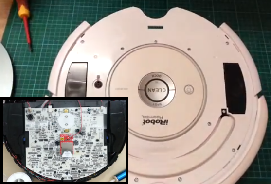
The Roomba, whom [Arthur] calls Colin, has been in service for a couple of years, and once he got his hands on the Electric Imp, he had just the project in mind.  With embedded Wi-Fi and a 32-bit processor all in an SD Card form factor, the Electric Imp makes it very easy to add the “Internet of Things” to just about anything you can think of.  [Arthur] wanted to gain control of the Roomba, so he tapped into the SCI (Serial Command Interface).  Now he can read out the Roomba’s on-board sensor data including battery voltage, current draw, and even the temperature.

These are the kind of walk-through’s we love to see, because he did it in real-time, so you get to experience all of the “surprises” along the way.  For example, he removed an external charging port to make room for the added components, but that ended up disabling the dock charger.  Then he discovered that when the Roomba was charging, the input voltage to the Electric Imp breakout board was too high, so he had to introduce an intermediate voltage regulator.  But perhaps the biggest bump in the road was when he accidentally brushed the Electric Imp breakout board along the Roomba’s control board while power was on.  Luckily the damage was isolated to just one smoked — a simple FET.  The project turned out great, and (today) Colin’s data is actually visible through a public Xively feed.

Continue reading “Giving A Roomba Internet Connectivity”

A Business Card That Plays Simon Says

BusinessCard_01_08

When your name is Simon and you want to build your own circuit board business card, it makes perfect sense to incorporate a game of Simon Says, and that’s exactly what [Simon] did with his Business Card.

You may see a resemblance to the Engineer’s Emergency Business Card; that’s because [Simon] took inspiration from that card to build his own.  The game of Simon Says is played via 4 low-profile pushbuttons and 4 0805 LEDs.  The microcontroller of choice to run the game is an ATtiny45 set up to work with the Arduino IDE.  But with only 5 pins available for I/O, [Simon] had to give up 4 pins to the LEDs and configure the remaining pin as an analog input.  The buttons are tied into a voltage divider that feeds the analog input, so depending which button is pressed, a different voltage is read in, thus a value from 0 to 1023 determines which button was pressed.

One of the great things about this write-up is that it goes through the process of etching PCBs at home using the toner-transfer method.  We’re not sure how many home-etched business cards he’s willing to pass out, but surely whoever does get the card, will never forget his name.

Continue reading “A Business Card That Plays Simon Says”

Arduino Ball Throwing Game

arduinogame01_07

Building your own gaming platform is pretty cool on its own, but when the game actually looks like fun to play, well that’s on a different level of cool. [Zippy314] designed an Arduino based game platform as a Christmas present to his son called the Das Blinken Bonken!

Like all highly addicting games, the gameplay is simple; the player throws a ball at the target board while aiming to hit a specific ‘pad’. As shown in the video after the break, there are many game possibilities with this platform, like trying to hit the illuminated target each time, or just trying to hit all of the pads on the board as fast as possible.

A pad is registered as a ‘hit’ with the help of home-made pressure sensors, which are each constructed in a ‘sandwich’ of pressure-sensitive conductive sheets. This is the same material used in these LED Sneakers. Since the resistance through the sheet lowers as pressure is applied, a simple voltage divider circuit is used to feed the analog inputs on the Arduino, thus making it very easy to detect a ‘hit’. An I2C 4-Digit 7 Segment display keeps score and displays the game title, while a strip of addressable RGB LEDs give player feedback and other vital gameplay information.

Continue reading “Arduino Ball Throwing Game”

Wireless Thermostat

thermostat0104

The thermostat in [Tom’s] 100-year-old house is two floors up from where the furnace is located, so a broken wire in the wall was just the catalyst needed to design a wireless thermostat.

The system is based on a customized PCB [Tom] designed called the Magic Mote. The board contains an MSP430 microcontroller, a low power NRF24l01+ wireless transceiver, and various sensor interfaces. The wireless thermostat project uses two of these boards; one monitors the temperature on the second floor and the other controls the furnace in the basement.

The temperature sensing is done using a DHT22/AM2303 temperature and humidity sensor, which is a convenient choice, since the part is calibrated and handles the analog digital conversion; you just need one digital pin to retrieve the temp/humidity data. To control the furnace, [Tom] used the local 24VAC and a latching relay to drive the heater signal. The 24VAC also powers the board, so a door-bell transformer steps the voltage down to something more usable; about 11VAC or so, which is then rectified, filtered, and regulated down to what the control electronics like to see (3.3V/5V).

This project is actually still in the early stages of what [Tom] has planned; a network of sensors and appliances with a beagle bone base station. We can’t wait to see what’s next for this project; maybe we’ll even see some voice control, like in this epic Siri controlled home automation project.

[via Dangerous Prototypes]

Building A Raspberry PI Digital Photo Frame

photoframe0103

Digital photo frames aren’t very interesting on their own these days, but building one with a Raspberry Pi and strapping it with a bunch of useful features just might motivate you to check out this tutorial on building a ‘living’ digital photo frame.

This is [Samuel’s] first project with the Raspberry Pi, so he decided to build a digital photo frame that has the ability to download random pictures from his Flicker account and display them in a slideshow format. With all that extra IO on the Raspi, it was easy to incorporate a status LED and PIR sensor. When motion is detected by the PIR sensor, the photo frame is enabled; after 60 seconds of no movement, the photo frame is disabled by turning off the monitor port.

We love finding detailed write-ups like this because there is so much useful information in here like using the Flicker API, GPIO control, image handling, how to configure scripts to run on boot-up, and even some great troubleshooting code.  If you’d rather ditch the Raspi altogether and take things down a few levels, check out this PIC based 100% DIY digital picture frame.

PhotoTransistor Based Eye-Tracking

eyetrack

The applications of eye-tracking devices are endless, which is why we always get excited to see new techniques in measuring the absolute position of the human eye. Cornell students [Michael and John] took on an interesting approach for their final project and designed a phototransistor based eye-tracking system.

We can definitely see the potential of this project, but for their first prototype, the system relies on both eye-tracking and head movement to fully control a mouse pointer. An end-product design was in mind, so the system consists of both a pair of custom 3D printed glasses and a wireless receiver; thus avoiding the need to be tethered to the computer under control . The horizontal position of the mouse pointer is controlled via the infrared eye tracking mechanism, consisting of an Infrared LED positioned above the eye and two phototransistors located on each side of the eye. The measured analog data from the phototransistors determine the eye’s horizontal position. The vertical movement of the mouse pointer is controlled with the help of a 3-axis gyroscope mounted to the glasses. The effectiveness of a simple infrared LED/phototransistor to detect eye movement is impressive, because similar projects we’ve seen have been camera based. We understand how final project deadlines can be, so we hope [Michael and John] continue past the deadline with this one. It would be great to see if the absolute position (horizontal and vertical) of the eye can be tracked entirely with the phototransistor technique.

Continue reading “PhotoTransistor Based Eye-Tracking”

Moody Useless Machine

If you ever get bored of trolling the internet seeking inspiration for your next big project, try a YouTube search of “useless machine”. After a few hours of watching these pointless, yet hilarious creations, we’re sure you’re going to want to build one. Luckily for us, [Arvid] documented the design of his moody useless machine to get you started.

Why is [Arvid’s] machine moody? Well, to fully appreciate the emotional sensitivity of a useless machine, you first need to understand what it is they do don’t do. A one sentence explanation is all that is needed here; you flip a switch and the machine flips the switch back… that’s it. [Arvid] implemented a two servo system with a stand-alone Arduino, which allowed him to give his machine a “personality”. Sometimes the switch is thrown back quickly without argument, other times the machine throws a fussy tantrum.

Although the machine is useless, the electronics inside are anything but. To keep everything clean and innocuous looking, the machine is powered by batteries, so [Arvid] places the Arduino into a ‘sleep’ mode until the switch is toggled. The switch is configured as an interrupt on the Arduino, which when toggled, wakes the Arduino.  Once the Arduino is awake, it enables power to the servos via a power MOSFET, then everything’s ready to go; the machine makes its response and goes back to ‘sleep’. This was a great project, but believe it or not, things can get more useless, like with this advanced useless machine.

Continue reading “Moody Useless Machine”