Final Project For Better Sleep

It’s that time of year again, and students around the world are scrambling (or have already scrambled) to finish their final projects for the semester. And, while studying for finals prevents many from sleeping an adequate amount, [Julia] and [Nick] are seeking to maximize “what little sleep the [Electrical and Computer Engineering] major allows” them by using their final project to measure sleep quality.

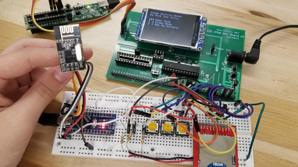
To produce a metric for sleep quality, [Julia] and [Nick] set out to measure various sleep-related activities, specifically heart rate, motion and breath frequency. During the night, an Arduino Nano mounted to a glove collects data from the various sensors mounted to the user, all the while beaming the data to a stationary PIC for analysis and storage. When the user awakes, they can view their sleep report on a TFT display at the PIC base station. Ideally, users would use this data to test different habits in order to get the best nights sleep possible.

Interestingly, the group chose to implement their own heart rate sensor. With an IR transmitter, IR phototransistor and an OP amp, the group illuminates user’s fingers and measure reflection to detect heartbeats. This works because the amount of IR reflected from the user’s finger changes with blood pressure and blood oxygen level, which also happen to change when the heart is beating. There were some bumps along the road when it came to the heartbeat sensor (the need to use a finger instead of the wrist forced them to use a glove instead of a wristband), but we think it’s super cool and totally worth it. In addition to heart rate, motion is measured by an accelerometer and breath is measured by a flex sensor wrapped around the user’s chest.

With all of their data beamed back by a pair of nRF24L01s, the PIC computes the sleep “chaos” which is exactly what it sounds like: it describes just how chaotic the user slept by looking for acyclic and sudden movement. Using this metric, combined with information from breathing and heart rate, the PIC computes a percentage for good sleep where 100% is a great night and 0% means you might have been just as well off pulling an all-nighter. And, to top it all off, the PIC saves your data to an SD card for easy after-the-fact review.

The commented code that powers the project can be found here along with a parts list in their project write-up.

This device assumes that sleeping is the issue, but if waking up if your problem, we’ve already got you covered, aggressive alarm clock style. For those already on top of their sleep, you might want some help with lucid dreaming.

Video of the project explained by [Julia] and [Nick] after the break.

Continue reading “Final Project For Better Sleep”

Car Lights For Reflow Heat Source

If you only have a car and you need to unsolder some tricky surface mount components: what would you do? If you’re Kasyan TV, you’d remove your car’s halogen lights and get to town. That’s right: car lights for reflow.

When the friend of the host of Kasyan TV needed to remove some roasted toasted FETs from his motherboard but didn’t have anything for reflowing, she took some headlights and used them as an infrared source to desolder the FETs. Powered by a lab supply (although car batteries work too), the process works with 60 and 100-watt bulbs.

Now, reflowing with halogen bulbs isn’t new, and we’ve seen it done with the run of the mill 100-watt bulbs and a halogen floodlight. However, what we really like about using car lights is that they’re available everywhere and we already own some that we could (temporarily) repurpose. Now, don’t get us wrong – if you’re going to be reflowing more than just a little, there are plenty of alternative methods that don’t involve staring at “rather bright lights” for extended periods of time.

People ’round these parts can’t seem to get enough of reflow: from open source reflow oven controllers to reflowing with a hair straightener we’ve seen quite a bit. If you’re new to the reflow arena, we’ve got zero to hero: reflow style just for you. And if DIY at home reflow isn’t intense enough for you, we’ve got next level reflowing as well.

The full video is after the break, complete with Kasyan TV’s sponsored segment in the middle..

Continue reading “Car Lights For Reflow Heat Source”

NFC Enabled Business Card

[Sjaak] is back at it again with the cool PCB business cards, this time alleviating the burden to physically type his contact information into your phone. But NFC isn’t the only cool thing on this PCB – as always, his aesthetics don’t disappoint.

When we see [Sjaak’s] card, the future seems to be the now – not only do we have business cards that can take our pulse, we have business cards that actively help facilitate the exchange of contact information. I know what you’re thinking. “Business cards made of paper do that already.” That’s true if you read them. You have to physically remember you have the card (aka not put it through the wash), and, if you’re like most folks, you’ll ultimately enter the information into your cell phone’s contact list. Why not skip the whole reading thing? You know, just zap your contact information into the contact list of people automatically?

Maybe this is exactly what [Sjaak] thought when he built his NFC enabled business card. Maybe not. Regardless, [Sjaak’s] card is beautiful – both in implementation and aesthetics. Powered by “a nice little NFC EEPROM from NXP”, (the NT3H1101) the business card even has an energy harvesting mode. Moreover, one can interact with the card via four buttons and an LED. The LED informs the user what mode the card is currently in, and the buttons choose which URL is sent to users via NFC. To add icing to the cake, the back of the PCB is decked out via [Sjaak’s] custom full-color decal process we covered back in August.

As great as it looks, the card still needs some improvement. “I still need to tackle the sharp and protruding components on the front, which will ruin your wallet.” But, in our eyes, the card is surely on its way to greatness, and we look forward to seeing its final form. However, if you’re anything like us, you might want to see some other rad PCB business cards while you wait. If that’s the case, we recommend this logic based finite machine and this card made by a hackaday author.

World’s Largest Telescope Stopped By LED

Earlier this year a simple indicator LED brought the Keck 1 telescope, a 370 tons mass, to a halting stop. How exactly did an LED do this? Simple: it did nothing.

As it so happens, [Andrew Cooper] was just about the leave the summit of Mauna Kea (in Hawaii) when his radio instructed him otherwise: there was an issue. Upon returning, [Andrew] was met by a room of scientists and summit supervisors. “Yeah, this was not good, why are they all looking at me? Oh, h%#*!” The rotor wasn’t moving the telescope, and “no rotator equals no science data.” After being briefed on the problem, [Andrew] got to work. Was it a mechanical issue? No: manual mode worked quite fine, also indicating that the amplifiers and limit switches are functional as well.

Jumping from chip to chip, [Andrew] came across an odd voltage: 9.36V. In the CMOS [Andrew] was investigating, this voltage should have High (15V) or Low (0v) and nowhere in between. Judging by the 9.36V [Andrew] decided to replace the driving IC. One DS3632 later, nothing had changed. Well, maybe is one of the loads pulling the line low? With only two choices, [Andrew] eliminated that possibility quickly. Likely feeling as if he was running out of proverbial rope, [Andrew] remembered something important: “the DS3236 driving this circuit is an open collector output, it needs a pull-up to go high.”

Reviewing the schematic, [Andrew] identified the DS3236’s pull-up: an LED and its current limiting resistor. While the carbon composition resistor was “armageddon proof,” [Andrew] was suspicious of the LED. “Nick, can you get me a 5k resistor from the lab?” Hold the resistor on the pins of the chip and the amplifiers immediately enabled.

[Andrew] summarizes things quite well: “yes… One of the world’s largest telescopes, 370 tons of steel and glass, was brought to a halt because of a bad indicator LED”. It stopped things by doing nothing, or rather, by not turning on.

We love it when we get troubleshooting stories, and if you share our interest in problem-solving, check out this broken power supply troubleshooting or learn what could go wrong with I2C.

Edit: Keck 1 is one of the largest optical telescopes in the world. Thanks to [Josh] for noticing our error.

A BluePill For Arduino Dependence

Arduinos are helpful but some applications require more than what Arduinos can provide. However, it’s not always easy to make the switch from a developed ecosystem into the abyss that is hardware engineering. [Vadim] noticed this, which prompted him to write a guide to shepherd people on their quest for an Arduino-free environment, one BluePill at a time.

With an extended metaphor comparing Arduino use and physical addiction, [Vadim’s] writing is a joy to read. He chose to focus on the BluePill (aka the next Arduino Killer™) which is a $1.75 ARM board with the form factor of an Arduino Nano. After describing where to get the board and it’s an accompanying programmer, [Vadim] introduces PlatformIO, an alternative to the Arduino IDE. But wait! Before the Arduino die-hards leave, take note that PlatformIO can use all of the “Arduino Language,” so your digitalWrites and analogReads are safe (for now). Like any getting started guide, [Vadim] includes the obligatory blinking an LED program. And, in the end, [Vadim] sets his readers up to be comfortable in the middle ground between Arduino Land and the Wild West.

The debate for/against Arduino has been simmering for quite some time, but most agree that Arduino is a good place to start: it’s simpler and easier than jumping head first. However, at some point, many want to remove their “crippling Arduino dependency” (in the words of [Vadim]) and move on to bigger and better things. If you’re at this point, or still cling to your Uno, swing on over and give Vadim’s post a read. If you’re already in the trenches, head on over and read our posts about the BluePill and PlatformIO which are great complements for [Vadim’s].

3D Printing T-Shirt Designs

Usually, t-shirt designs are screen printed, but that’s so old school. You have to make the silkscreen and then rub paint all over – it’s clearly a technique meant for the past. Well, fear not, as [RCLifeOn] is here to bring us to the future with 3D Printed T-Shirt Designs.

[RCLifeOn] affixes t-shirts to his print build platform and boom: you’ve got 3D printed graphics. He started by using PLA which, while it looked great, wasn’t up to a tussle with a washing machine. However, he quickly moved on to NinjaFlex which fended much better in a wash cycle. While the NinjaFlex washed better, [RCLifeOn] did have some issues getting the NinjaFlex to adhere to the t-shirt. With a little persistence and some settings tweaking, he was able to come out ahead with a durable and aesthetically pleasing result.

Now, 3D printing isn’t going to replace screen printing, but it’s also not going to replace injection molding. What 3D printing lacks in speed and efficiency, it makes up in setup time & cost. In other words, if you need 50 t-shirts of the same design, screen printing is the way to go. But, if you need 50 shirts, each with a different design, you just might want to follow in [RCLifeOn’s] footsteps.

Anyways, we don’t have much on 3D printing t-shirts, but we do have other useful information on 3D printing slinkys and 3D printing project enclosures. And, if you’d rather do it the old-school way, we can show you how to silkscreen all the things.

A Detailed Guide For 3D Printing Enclosures

We’ve all have projects that are done, but not complete. They work, but they’re just a few PCBs wired together precariously on our desks. But fear not! A true maker’s blog has gifted us with a detailed step-by-step guide on how to make a project enclosure.

Having purchased an MP Select Mini 3D Printer, there was little to do but find something practical to print. What better than an enclosure for a recently finished Time/Date/Temperature display Arduino based device?

The enclosure in this guide, while quite nice, isn’t the main attraction here. The real feature is the incredibly detailed instructions for how to design, model and print an enclosure for any project. For the veterans out there, it seems simple. Sketch something on the back of a napkin and take a nap on your keyboard with OpenSCAD open. When you wake, BAM: perfect 3D model. However, for newcomers, the process can seem daunting. With incredibly specific instructions (an example is “Open up a new workspace by clicking CREATE NEW DESIGN,” notice the accurate capitalization!), it should ease the barrier of the first enclosure, turning the inexperienced into the kind-of-experienced.

If you’ve been printing enclosures since the dawn of time or plastic simply isn’t your style, boy, do we have you covered. Why not check out FR4 (aka PCB) enclosures? Or what about laser cut enclosures from eagle files? Maybe two-piece boxes are more your thing.