Developing An Automatic Tool For CAN Bus Hacking

In the old days, a physical button or switch on the dashboard of your car would have been wired to whatever device it was controlling. There was potentially a relay in the mix, but still, it wasn’t too hard to follow wires through the harness and figure out where they were going. But today, that concept is increasingly becoming a quaint memory.

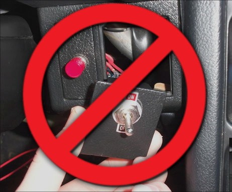
Assuming your modern car even has physical buttons, pushing one of them likely sends a message over the CAN bus that the recipient device will (hopefully) respond to. Knowing how intimidating this can be to work with, [TJ Bruno] has been working on some software that promises to make working with CAN bus user interfaces faster and easier. Ultimately, he hopes that his tool will allow users to rapidly integrate custom hardware into their vehicle without having to drill a hole in the dashboard for a physical control.

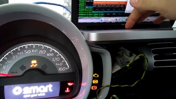
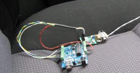
But if you’re the kind of person who doesn’t like to have things done for them (a safe bet, since you’re reading Hackaday), don’t worry. [TJ] starts off his write-up with an overview of how you can read and parse CAN messages on the Arduino with the MCP2515 chip. He breaks his sample Sketch down line by line explaining how it all works so that even if you’ve never touched an Arduino before, you should be able to get the gist of what’s going on.

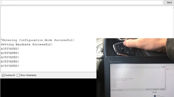
As it turns out, reading messages on the CAN bus and acting on them is fairly straightforward. The tricky part is figuring out what you’re looking for. That’s where the code [TJ] is working on comes in. Rather than having to manually examine all the messages passing through the network and trying to ascertain what they correspond to, his program listens while the user repeatedly presses the button they want to identify. With enough samples, the code can home in on the proper CAN ID automatically.

The upside to all this is that you can activate aftermarket functions or hardware with your vehicle’s existing controls. Need an example? Check out the forward-looking camera that [TJ] added to his his 2017 Chevy Cruze using the same techniques.

Continue reading “Developing An Automatic Tool For CAN Bus Hacking”

Reverse-Engineering The Peugeot 207’s CAN Bus

Here’s a classic “one thing led to another” car hack. [Alexandre Blin] wanted a reversing camera for his old Peugeot 207 and went down a rabbit hole which led him to do some extreme CAN bus reverse-engineering with Arduino and iOS. Buying an expensive bezel, a cheap HDMI display, an Arduino, a CAN bus shield, an iPod touch with a ghetto serial interface cable that didn’t work out, a HM-10 BLE module, an iPad 4S, the camera itself, and about a year and a half of working on it intermittently, he finally emerged poorer by about 275€, but victorious in a job well done. A company retrofit would not only have cost him a lot more, but would have deprived him of everything that he learned along the way.

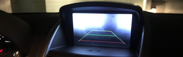
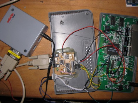
Adding the camera was the easiest part of the exercise when he found an after-market version specifically meant for his 207 model. The original non-graphical display had to make room for a new HDMI display and a fresh bezel, which cost him much more than the display. Besides displaying the camera image when reversing, the new display also needed to show all of the other entertainment system information. This couldn’t be obtained from the OBD-II port but the CAN bus looked promising, although he couldn’t find any details for his model initially. But with over 2.5 million of the 207’s on the road, it wasn’t long before [Alexandre] hit jackpot in a French University student project who used a 207 to study the CAN bus. The 207’s CAN bus system was sub-divided in to three separate buses and the “comfort” bus provided all the data he needed. To decode the CAN frames, he used an Arduino, a CAN bus shield and a python script to visualize the data, checking to see which frames changed when he performed certain functions — such as changing volume or putting the gear in reverse, for example.

The Arduino could not drive the HDMI display directly, so he needed additional hardware to complete his hack. While a Raspberry Pi would have been ideal, [Alexandre] is an iOS developer so he naturally gravitated towards the Apple ecosystem. He connected an old iPod to the Arduino via a serial connection from the Dock port on the iPod. But using the Apple HDMI adapter to connect to the display broke the serial connection, so he had to put his thinking cap back on. This time, he used a HM-10 BLE module connected to the Arduino, and replaced the older iPod Touch (which didn’t support BLE) with a more modern iPhone 4S. Once he had all the bits and pieces working, it wasn’t too long before he could wrap up this long drawn upgrade, but the final result looks as good as a factory original. Check out the video after the break.

It’s great to read about these kinds of hacks where the hacker digs in his feet and doesn’t give up until it’s done and dusted. And thanks to his detailed post, and all the code shared on his GitHub repository, it should be easy to replicate this the second time around, for those looking to upgrade their old 207. And if you’re looking for inspiration, check out this great Homemade Subaru Head Unit Upgrade.

Continue reading “Reverse-Engineering The Peugeot 207’s CAN Bus”

Reverse Engineering The Smart ForTwo CAN Bus

The CAN bus has become a defacto standard in modern cars. Just about everything electronic in a car these days talks over this bus, which makes it fertile ground for aspiring hackers. [Daniel Velazquez] is striking out in this area, attempting to decode the messages on the CAN bus of his Smart ForTwo.

[Daniel] has had some pitfalls – first attempts with a Beaglebone Black were somewhat successful in reading messages, but led to strange activity of the car and indicators. This is par for the course in any hack that wires into an existing system – there’s a high chance of disrupting what’s going on leading to unintended consequences.

Further work using an Arduino with the MCP_CAN library netted [Daniel] better results, but  it would be great to understand precisely why the BeagleBone was causing a disturbance to the bus. Safety is highly important when you’re hacking on a speeding one-ton metal death cart, so it pays to double and triple check everything you’re doing.

Thus far, [Daniel] is part way through documenting the messages on the bus, finding registers that cover the ignition and turn signals, among others. Share your CAN hacking tips in the comments. For those interested in more on the CAN bus, check out [Eric]’s great primer on CAN hacking – and keep those car hacking projects flowing to the tip line!

Router Controlling Choo-choos Over The CAN Bus

This setup is used to control a model railroad. Well, not entirely this setup. [Gerhard Bertelsmann] already has a proper railroad controller, and it just happens to offer CAN bus communications. He’s using OpenWRT and a cheap router to connect the bus to the network.

Originally he wanted to use a Raspberry Pi board for the project, but the incredible backorder  situation with that hardware led him to grab an old router. After loading OpenWRT he started working out how to connect a couple of ICs (MCP2515 and MCP2551) that will take care of the CAN bus communications. The hardware connections end up being pretty simple, with five data lines (and their pull-up resistors) connecting to the router’s serial header. From there it was a matter of mapping the device in software so that the hardware can be controlled over the network.

We like this example since CAN is used is a lot of other applications.

Tinkering With ODB II And The CAN Bus

[Debrah] is taking his next project out to the garage. He built his own CAN bus reader using a dsPIC.

The nice thing about working with Control Area Network is that it’s a universal standard found on every modern production line automobile. And because of this, the chip you need in order to communicate using that protocol will cost just over a dollar. [Debraj] chose the MCP2551, which comes in several different 8-pin packages. There is even an application note tailored for use with the dsPIC33F family.

The project is running on both 5V and 3.3V rails. This complicates things just a bit, but a level converter makes sure that there’s no communications problems between the chips. A four line character LCD acts as the output during the tests (you can see this in the clip after the break) but he’s already got a second version which looks quite a bit better on the dashboard.

What else can be done with this hack? Well, we’ve seen a method used to read control buttons from the steering wheel before. It all depends on what data your vehicle is transmitting and one way to find that out is to build some hardware and start logging the packets. Continue reading “Tinkering With ODB II And The CAN Bus”

CAN Bus For Home Automation

Here’s one node on the new home automation system on which [Black Rynius] is working. So far he’s testing out the system with just two nodes, but plans to build more as the project progresses. He’s chosen to use the CAN bus for communications; a protocol which is most commonly found in automotive applications.

The biggest plus about using the CAN bus is that it requires just one pair of wires for communications. As you can see, there’s an old doorbell included on this board and he’s hoping to use the existing doorbell wire to connect between nodes. Each unit includes a PIC 18F4580 which has a CAN engine built into it for easy protocol translation. There is also an MCP2551 which handles the transmissions. You can read a bit more about the hardware choices in his breadboarding post.

So far almost everything is working as planned. He’s able to send and receive data between the two boards including temperature from a sensor and time from a DS1305 RTC chip. The one thing that vexes him is that doorbell. It draws too much current for the wall wart that’s powering the board, browning out the microcontroller and causing a reset. That’s not a hard fix and we look forward to more developments in the near future.

[via Dangerous Prototypes]

can_bus_hacking

Enhance Your Key Fob Via CAN Bus Hacking

[Igor] drives a 4th generation Volkswagen Golf, and decided he wanted to play around with the CAN bus for a bit. Knowing that the comfort bus is the most accessible and the safest to toy with, he started poking around to see what he could see (Google translation).

He pulled the trim off one of the rear doors and hooked into the comfort bus with an Arudino and a CAN interface module. He sniffed the bus’ traffic for a bit, then decided he would add some functionality to the car that it was sorely lacking. The car’s windows can all be rolled down by turning the key in any lock for more than a few seconds, however this cannot be done remotely. The functionality can be added via 3rd party modules or through manipulating the car’s programming with some prepackaged software, but [Igor] wanted to give it a go himself.

He programmed the Arduino to listen for longer than normal button presses coming from the remote. Once it detects that he is trying to roll the windows up or down, the Arduino issues the proper window control commands to the bus, and his wish is the car’s command.

It’s a pretty simple process, but then again he has just gotten started. We look forward to seeing what else [Igor] is able to pull off in the future.  In the meantime, continue reading to see a quick video of his handiwork.

If you are interested in seeing what you might be able to do with your own car, check out this CAN  bus sniffer we featured a while back.

Continue reading “Enhance Your Key Fob Via CAN Bus Hacking”