When Is Damascus Steel Not From Damascus?

If you grow up around a working blacksmith’s forge, there are a few subjects related to metalwork on which you’ll occasionally have a heated discussion. Probably the best known is the topic of wrought iron, a subject I’ve covered here in the past, and which comes from the name of a particular material being confused with a catch-all term of all blacksmith-made items. I’ve come to realise over recent years that there may be another term in general use which is a little jarring to metalwork pedants, so-called Damascus steel. Why the Syrian capital should pop up in this way is a fascinating story of medieval metalworking, which can easily consume many days of research.

Damascus? Where’s That?

A section of a knife blade with various silver grey and black layered patterns in the metal.
The banded pattern of the laminate formed from pattern welded layers of differing steels in a modern Damascus steel knife. “DamaszenerKlinge” by Soerfm

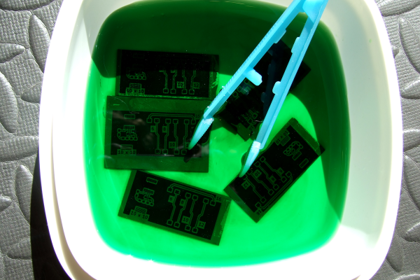
The Damascus steel you’ll see in YouTube videos, TV shows, and elsewhere is a steel with complex bands and striations on its surface. It’s often used in knife blades, and it will usually have been chemically treated to enhance the appearance of the patterns. It’s a laminate material made by pattern welding layers of different steels together, and it will usually have been worked and folded many times to produce a huge number of very thin layers of those steels. Sometimes it’s not made from sheets or ingots of steel but from manufactured steel products such as chains, in an attempt to produce a result with more unusual patterns. Continue reading “When Is Damascus Steel Not From Damascus?”

USB-C For Hackers: Build Your Own PSU

What if you wanted to build your own USB-C PSU? Good news – it’s easy enough! If you ever wanted to retrofit a decent DC PSU of yours to the USB-C standard, say, you got a Lenovo/HP/Dell 19V-20V charger brick and you’ve ever wished it were USB-C, today is the day when we do exactly that. To be fair, we will cheat a bit – but only a tiny bit, we won’t be deviating too much from the specification! And, to begin with, I’ll show you some exceptionally easy ways that you can turn your DC PSU into a USB-C compatible one, with a simple module or a few.

Turning a 20 V PSU into a USB-C PSU feels natural if you want to charge a laptop – those tend to request 20 V from a USB-C PSU anyway, so what’s the big deal? However, you can’t just put 20 V onto a USB-C connector – you have to add a fair bit of extra logic to make your newly christened USB-C PSU safe to use with 5 V devices, and this logic also requires you go through a few extra steps before 20 V appears on VBUS. Any USB-C PSU has to output 5 V first and foremost whenever a device is connected, up until a higher voltage is negotiated digitally, and the PSU may only switch to a higher voltage output when it’s requested to do so.

Now, for that, a PSU offers a list of profiles, and we looked into those profiles in the Replying PD article – each profile is four bytes that contain information about the profile voltage, maximum current that the device may draw at that voltage, and a few other details. For a PSU to be USB-C compliant, the USB-C specification says that, in addition to 5 V, you may also offer 9 V, 15 V, and 20 V.

Also, the specification says that if a PSU supports certain in-spec voltage like 15 V, it’s also required by the spec to offer all of the spec-defined voltages below the maximum one – for 15 V, that also requires supporting 9 V. Both of these are UX requirements, as opposed to technical requirements – it’s easier for device and PSU manufacturers to work with a small set of pre-defined voltages that majority of the chargers will support, but in reality, you can actually offer any voltage you want in the PSU advertisement; at worst, a device is going to refuse and contend with slowly charging from the 5 V output that you’re required to produce.

I’d like to walk you through how off-the-shelf USB-C PSUs work, all of the options you can use to to create one, and then, let’s build our own USB-C PSU from scratch! Continue reading “USB-C For Hackers: Build Your Own PSU”

Chip Shortage Engineering: Misusing DIP Packages

After years of seeing people showing off and trading their badge Simple Add-Ons (SAOs) at Supercon, this year I finally decided to make one myself. Now for a first attempt, it would have been enough to come up with some cool PCB art and stick a few LEDs on it. But naturally I started with a concept that was far more ambitious than necessary, and before long, had convinced myself that the only way to do the thing justice was to have an onboard microcontroller.

My first thought was to go with the venerable ATtiny85, and since I already had a considerable stock of the classic eight-pin DIP MCUs on hand, that’s what I started prototyping with. After I had something working on the breadboard, the plan was to switch over to the SOIC-8 version of the chip which would be far more appropriate for something as small as an SAO.

Unfortunately, that’s where things got tricky. I quickly found that none of the major players actually had the SMD version of the chip in stock. Both DigiKey and Mouser said they didn’t expect to get more in until early 2024, and while Arrow briefly showed around 3,000 on hand, they were all gone by the time I checked back. But that was only half the problem — even if they had them, $1.50 a piece seems a hell of a lot of money for an 8-bit MCU with 8K of flash in 2023.

The whole thing was made all the more frustrating by the pile of DIP8 ATtiny85s sitting on the bench, mocking me. Under normal circumstances, using them in an SAO wouldn’t really be a problem, but eight hand-soldered leads popping through the front artwork would screw up the look I had in mind.

While brooding over the situation my eyes happened to fall on one of the chips I had been fiddling with, it’s legs badly bent from repeated trips through the programmer. Suddenly it occurred to me that maybe there was a way to use the parts I already had…

Continue reading “Chip Shortage Engineering: Misusing DIP Packages”

A Pulse Of Annoyance About Oscillators, Followed By A Flyback Of A Rant

Everyone likes to play with high voltages, right?. Even though the danger of death goes up with every volt, it’s likely that a few readers will have at some time or other made fancy long sparks. You’re reading this so you lived to tell the tale, and we’d only ever counsel only doing so safely, but the point of this piece lies not in the volts themselves but in a touch of frustration at the voltage generators. There’s a circuit I see so often which annoys me every single time, so here if you don’t mind I’m going to deliver both a little rant and a look into flyback converters.

It’s Got Coils, so It’s A Transformer

A power supply with the lid removed, visible is a large transformer
Linear power supplies with a mains transformer are a surprisingly rare sight now. Dilshan Jayakody, CC BY-SA 2.0.

How does a transformer work? An alternating current in a primary winding induces an opposite current in its secondary winding. The voltage out is equal to the turns ratio times the voltage in. Thus if you want to make a high voltage, it’s simply a case of finding a transformer with the right turns ratio, and applying the right AC to the input.

A handy choice for a high voltage transformer has been for years a TV line output transformer, also sometimes known as a flyback transformer. You could find these in CRT displays and TVs, and they consist of a square ferrite core with a big chunky high voltage overwinding for the CRT anode circuit and a load of lower voltage windings. TV designers were always out to save on parts costs, so they often had windings for all the voltage rails inside the set as well as the anode voltage, using the timebase as a crude switching power supply. Continue reading “A Pulse Of Annoyance About Oscillators, Followed By A Flyback Of A Rant”

Logic Analyzers: Capabilities And Limitations

Last time, we’ve used a logic analyzer to investigate the ID_SD and ID_SC pins on a Raspberry Pi, which turned out to be regular I2C, and then we hacked hotplug into the Raspberry Pi camera code with an external MCU. Such an exercise makes logic analyzers look easy, and that’s because they are! If you have a logic analyzer, you’ll find that a whole bunch of hacks become available to you.

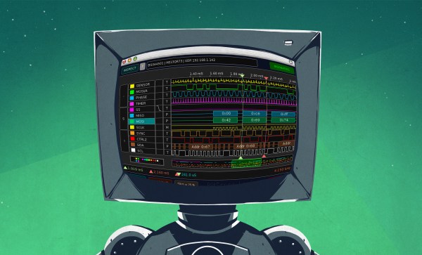
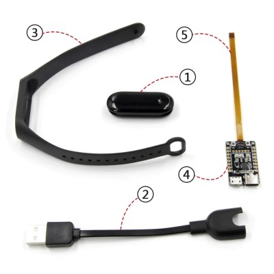
In this article, let’s figure out places where you can use a logic analyzer, and places where you can’t. We’ll start with the first limitation of logic analyzers – capture speed. For instance, here’s a cool thing you can buy on Aliexpress – a wristband from TTGO that looks like a usual fitness tracker, but has an ESP32 in it, together with an IMU, an RTC, and an IPS screen! The seller also has an FFC-connectable devboard for programming this wristband over UART, plus vibromotor and heartrate sensor expansion modules.

You can run C, MicroPython, Rust, JavaScript, or whatever else – just remember to bring your own power saving, because the battery is super small. I intended to run MicroPython on it, however, and have stumbled upon a problem – the ST7735-controller display just wouldn’t work with the st7735.py library I found; my image would be misaligned and inverted.

The specifications didn’t provide much other than “ST7735, 80×160”. Recap – the original code uses an Arduino (C++) ST7735 library and works well, and we have a MicroPython ST7735 library that doesn’t. In addition to that, I was having trouble getting a generic Arduino ST7735 library to work, too. Usually, such a problem is caused by the initialization commands being slightly different, and the reason for that is simple – ST7735 is just the name of the controller IC used on the LCD panel.

Each display in existence has specifics that go beyond the controller – the pixels of the panel could be wired up to the controller in a bunch of different ways, with varying offsets and connection types, and the panel might need different LCD charge pump requirements – say, depending on the panel’s properties, you might need to write 0x10 into a certain register of the ST7735, or you will need 0x40. Get one or more of these registers wrong, and you’ll end up with a misaligned image on your display at best, or no output at worst. Continue reading “Logic Analyzers: Capabilities And Limitations”

Copper Be Gone: The Chemistry Behind PCB Etching

For a lot of reasons, home etching of PCBs is somewhat of a dying art. The main reason is the rise of quick-turn PCB fabrication services, of course; when you can send your Gerbers off and receive back a box with a dozen or so professionally made PCBs for a couple of bucks, why would you want to mess with etching your own?

Convenience and cost aside, there are a ton of valid reasons to spin up your own boards, ranging from not having to wait for shipping to just wanting to control the process yourself. Whichever camp you’re in, though, it pays to know what’s going on when your plain copper-clad board, adorned with your precious artwork, slips into the etching tank and becomes a printed circuit board. What exactly is going on in there to remove the copper? And how does the etching method affect the final product? Let’s take a look at a few of the more popular etching methods to understand the chemistry behind your boards.

Continue reading “Copper Be Gone: The Chemistry Behind PCB Etching”

Share Your Projects: Leave Breadcrumbs

I’ve talked about a low-effort way to document your projects by taking plenty of pictures, and about ways that your PCBs could be documenting themselves. Today, let’s talk about a quick and easy way that you could help other hackers as you go through your own hacking adventures — leaving breadcrumbs.

In short, breadcrumbs are little pieces of crucial information that you had to spend time to figure out. They are solutions to problems that another hacker just like you could stumble upon in the future, something that you perhaps wish you didn’t have to figure out on your own, and certainly something that others won’t need to spend time figuring out.

Breadcrumbs are about saving time, for you and others. It helps if you think of your solved problems in terms of time spent. If you figure out a small problem and then publish your solution, you might be saving half an hour, a full hour, or a good few hours of time another hacker that’s could even be less experienced in debugging than you. In fact, your breadcrumb might even make a difference between someone completing a project and abandoning it!

However, there’s also the trade-off of taking time to document something. If you can’t publish your solution in a few minutes’ time, it might become much harder to persuade your brain to publish the next time you have something notable. Here’s a guideline: if you’ve just figured out a cool terminal command that helps you solve a certain kind of problem, you should have a quick way to publish that command within a minute. The good news is, the internet has a hundred different places you could easily share your findings, depending on the kind of problem you’ve solved! Continue reading “Share Your Projects: Leave Breadcrumbs”