Building And Controlling 19 LEDs & Five Buttons From Five Outputs

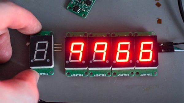
Numbers are hard enough in English, but [Sadale] decided to take things a step further by building a calculator that works in Toki Pona. The result is Ilo Nanpa, an awesome hardware calculator that works in this synthetic minimal language. This is a bit harder than you might think, because Toki Pona doesn’t have digits in the same way that Neo-Latin languages like English do. Instead, you combine smaller numbers to make bigger ones. One is Wan, Two is Tu, but three is Wan Tu (1+2). As you might expect, this makes dealing and representing larger numbers somewhat complicated.

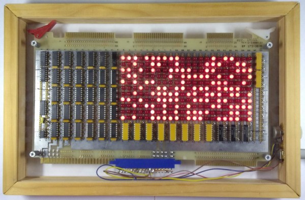
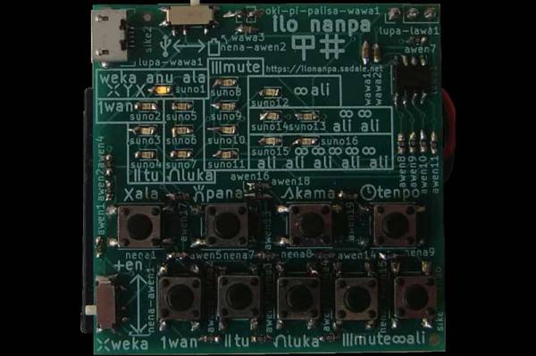
Ilo Nanpa gets around this in a wonderfully elegant way, and with some impressive behind the scenes work. The calculator has 16 LEDs, nine buttons and a slider switch, but they are all controlled and read through just five IO pins on the STM8S001J3 controller that runs the device.

That’s because {Sadale] did some remarkable work with multiplexing and charlieplexing. Multiplexing is controlling more outputs than there are control inputs by using rows and columns: it is how the LED display you are probably reading this on can be controlled by just a few wires. By switching through these rows and columns at a higher speed than the eye can see, you create the illusion of a single, continuous display.

Charlieplexing takes this a step further by using multiple voltages on a single connection to further split the signal. With the clever use of voltage dividers the directional properties of LEDs and multiple voltage levels, the Ilo Nanpa runs all of the LEDs and senses all of the buttons and the slider from just five pins. That’s a remarkably neat piece of design, and it is worth spending some time looking over the excellent explanation of the process that [Sadale] wrote to see how it is done, and poring over the code for the device to see how he programmed this all into a single low powered chip. And, while you are reading, you might pick up a few words of Toki Pona. Tawa Pona!

Continue reading “Building And Controlling 19 LEDs & Five Buttons From Five Outputs”

Hackaday Superconference: Estefannie’s Daft Punk Helmet

There’s no single formula for success, but if we’ve learned anything over the years of covering cons, contests, and hackathons, it’s that, just like in geology, pressure can create diamonds. Give yourself an impossible deadline with high stakes, and chances are good that something interesting will result. That’s what Estefannie from the YouTube channel “Estefannie Explains It All” did when Bay Area Maker Faire was rolling around last year, and she stopped by the 2018 Hackaday Superconference to talk about the interactive Daft Punk helmet that came out of it.

It’s a rapid-fire tour of Estefannie’s remarkably polished replica of the helmet worn by Guy-Manuel de Homem-Christo, one half of the French electronic music duo Daft Punk. Her quick talk, video of which is below, gives an overview of its features, but we miss the interesting backstory. For that, the second video serves as a kickoff to a whirlwind month of hacking that literally started from nothing.

You’ll Learn it Along the Way

Before deciding to make the helmet, Estefannie had zero experience in the usual tools of the trade. With only 28 days to complete everything, she had to: convert her living room into a workshop; learn how to 3D print; print 58 separate helmet parts, including a mold for thermoforming the visor; teach herself how to thermoform after building the tools to do so; assemble and finish all the parts; and finally, install the electronics that are the hallmark of Daft Punk’s headgear.

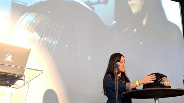
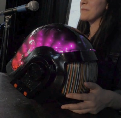
The three videos in her series are worth watching to see what she put herself through. Estefannie’s learning curve was considerable, and there were times when nothing seemed to work. The thermoforming was particularly troublesome — first too much heat, then not enough, then not enough vacuum (pretty common hurdles from other thermoforming projects we’ve seen). But the finished visor was nearly perfect, even if it took two attempts to tint.

We have to say that at first, some of her wounds seemed self-inflicted, especially seeing the amount of work she put into the helmet’s finish. But she wanted it to be perfect, and the extra care in filling, sanding, priming, and painting the printed parts really paid off in the end. It was down to the wire when BAMF rolled around, with last minute assembly left to the morning of the Faire in the hotel room, but that always seems to be the way with these kinds of projects.

In the end, the helmet came out great, and we’re glad the run-up to the Superconference wasn’t nearly as stressful for Estefannie — or so we assume. And now that she has all these great new skills and tools, we’re looking forward to her next build.

Continue reading “Hackaday Superconference: Estefannie’s Daft Punk Helmet”

You’ll Never See The End Of This Project

…theoretically, anyway. When [Quinn] lucked into a bunch of 5 mm red LEDs and a tube of 74LS164 shift registers, a project sprang to mind: “The Forever Number,” a pseudo-random number generator with a period longer than the age of the universe. Of course, the components used will fail long before the sequence repeats, but who cares, this thing looks awesome!

Check out the gorgeous wire-wrapping job!

The core of the project is a 242-bit linear-feedback shift register (LFSR) constructed from (31) 74LS164’s. An XOR gate and inverter computes the next bit of the sequence by XNOR’ing two feedback bits taken from taps on the register, and this bit is then fed into bit zero. Depending on which feedback taps are chosen, the output sequence will repeat after some number of clock cycles, with special sets of feedback taps giving maximal lengths of 2N – 1, where N is the register length. We’ll just note here that 2242 is a BIG number.

The output of the LFSR is displayed on a 22×11 array of LEDs, with the resulting patterns reminiscent of retro supercomputers both real and fictional, such as the WOPR from the movie “War Games,” or the CM2 from Thinking Machines.

The clock for this massive shift register comes from – wait for it – a 555 timer. A potentiometer allows adjustment of the clock frequency from 0.5 to 20 Hz, and some extra gates from the XOR and inverter ICs serve as clock distribution buffers.

We especially love the construction on this one. Each connection is meticulously wire-wrapped point-to-point on the back of the board, a relic originally intended for an Intel SBC 80/10 system. This type of board comes with integrated DIP sockets on the front and wire-wrap pins on the back, making connections very convenient. That’s right, not a drop of solder was used on the board.

You can see 11 seconds of the pattern in the video after the break. We’re glad [Quinn] didn’t film the entire sequence, which would have taken some 22,410,541,156,499,040,202,730,815,585,272,939,064,275,544, 100,401,052,233,911,798,596 years (assuming a 5 Hz clock and using taps on bits 241 and 171 ).

Continue reading “You’ll Never See The End Of This Project”

CNC Turns A Single PCB Into Origami Hemisphere

Trying to make a hemispherical surface out of a PCB is no easy feat. Trying to do that and make the result a working circuit is even harder. Doing it with one solid piece of FR4 seems impossible, right?

Not so much. [brainsmoke] came up with a clever way to make foldable, working PCBs that can be formed into hemispheres. The inspiration for this came from a larger project that resulted in a 32-cm diameter LED-studded sphere, which a friend thought would make a swell necklace if it was scaled down. That larger sphere was made somewhat like a PCB soccer ball, with individual panels soldered together. [brainsmoke] didn’t relish juggling dozens of tiny PCBs to make a necklace-sized version, so the unfolded pattern for half a deltoidal hexecontahedron was laid out as one piece on single-sided FR4. The etched boards were then cut out on a CNC mill, with the joints between the panels cut as V-grooves from the rear of the board. By leaving just enough material to act as a live hinge, [brainsmoke] was able to fold the pattern up into a hemisphere while leaving the traces intact. The process was fussy and resulted in a lot of broken FR4 and traces, but with practice and the use of thicker board material and heavier copper, the hemisphere came together. The video below shows the final product

This objet d’art is [brainsmoke]’s entry in the Circuit Sculpture Contest, which is just wrapping up wrapped up last week. We can’t wait to share some of the cool things people came up with in this contest, which really seemed to get the creative juices flowing.

Continue reading “CNC Turns A Single PCB Into Origami Hemisphere”

Hot Glue Makes These Segments Glow

It’s safe to say that hot-melt glue is a staple of the projects we see here at Hackaday. There won’t be many readers who don’t have a glue gun, and a blob of the sticky stuff will secure many a project. But it’s not so often we see it used as an integral component for a property other than its stickiness, so [DusteD]’s reaction timer project is interesting for having hot glue as a translucent light guide and diffuser for its LED seven-segment display.

The timer is simple enough, being driven by an Arduino board, while the display is pre-formed into the 3D-printed case. The hot glue fills the enclosures behind each segment, and after several experiments it was found that the best filling method was from behind against a piece of Kapton tape. The LEDs were wired into a common cathode array, and along with the arcade-style button and the Arduino the whole fitted neatly in the box. You can see the result in action in the video below the break.

Of course, this display is unusual for its use of hot glue, but not unique. We’ve seen a different take on a hot glue light pipe display before.

Continue reading “Hot Glue Makes These Segments Glow”

Addressable 7-Segment Displays May Make Multiplexing A Thing Of The Past

[Sean Hodgins] has a knack for coming up with simple solutions that can make a big difference, but this is one of those “Why didn’t I think of that?” things: addressable seven-segment LED displays.

[Sean]’s design is basically a merging of everyone’s favorite Neopixel RGB LED driver with the ubiquitous seven-segment display. The WS2811 addressable RGB driver chip doesn’t necessarily have to drive three different color LEDs – it can drive three segments of the same display. With three of the chips on a single board, all seven segments plus the decimal point of a display can be controlled over a single data line. No more shift registers, no more multiplexing. And as a nice touch, individual displays can be ganged together with connectors on the back of each module. [Sean] has some code to support the display but is looking for someone to build a standalone library for it, so you might want to pitch in. Yes, he plans to sell the boards in his shop, but as with all his projects, this one is open source and everything you need to build your own is up on GitHub. The brief video below shows a few daisy-chained displays in action.

Like many of [Sean]’s designs, including this Arduino rapid design board, this is a simple way to get a tedious job done, and it wrings a lot of functionality from a single IO pin.

Continue reading “Addressable 7-Segment Displays May Make Multiplexing A Thing Of The Past”

WiFi Remote Control Those Cheap LED Strips With An ESP8266 Passthrough

The explosion of cheap LED lighting products has given a never-ending array of opportunities for the resourceful hacker. A few dollars can secure strings of colourful illumination, but without further expenditure they lack the extra utility of electronic control. This is something that [Albert David has addressed] with his simple ESP8266-based WiFi switcher that he’s added to a string of USB-powered LEDs, and he’s neatly mounted the ESP-12 module it used atop a USB plug.

The circuitry is pretty straightforward, with only a couple of I/O lines being used. A transistor takes care of the heavy lifting, and the software comes courtesy of the Tasmota firmware for Sonoff (and similar) devices. We suspect with this economy of connection, the same task could be achieved even with the limited resources provided by the lesser ESP-01 module.

There was a time not so long ago when performing a task such as controlling a light over a wireless network involved significant cost, power, and complexity. In the nearly five years since we reported on the arrival of the ESP8266 we have progressed to the point at which that task is a simple project using commodity components, and that represents something of a miracle.