WSPR To The Wind With A Pi Pico High Altitiude Balloon

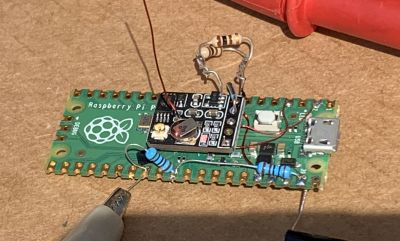
They say that if you love something, you should set it free. That doesn’t mean that you should spend any more on it than you have to though, which is why [EngineerGuy314] put together this Raspberry Pi Pico high-altitude balloon tracker that should only set you back about $12 to build.

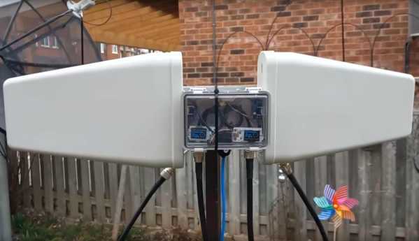
This simplified package turns a Pico into a tracking beacon — connect a cheap GPS module and solar panel, and the system will transmit the GPS location, system temperature, and other telemetry on the 20-meter band using the Weak Signal Propagation Reporter (WSPR) protocol. Do it right, and you can track your balloon as it goes around the world.

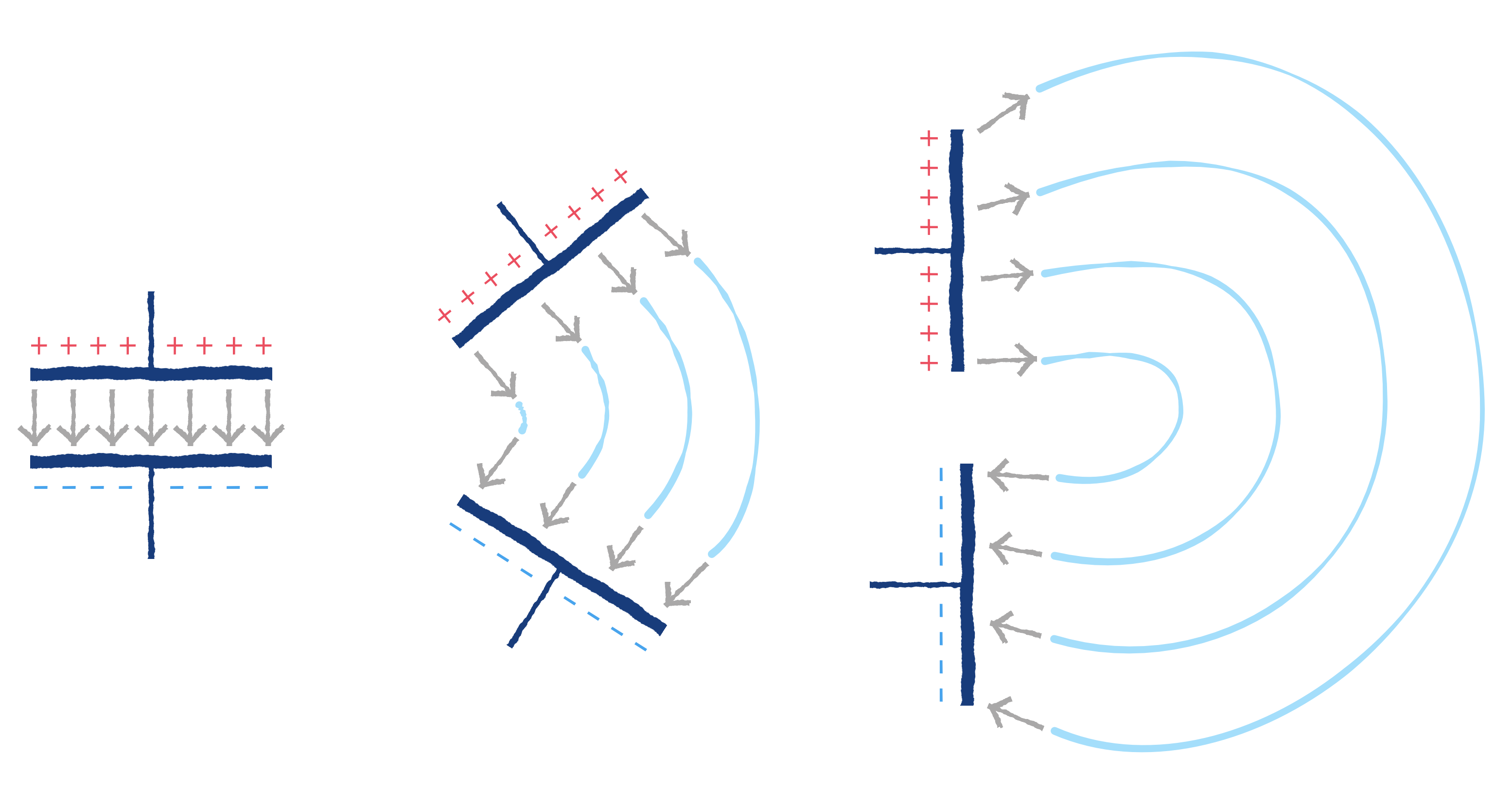
The project is based in part on the work of [Roman Piksayin] in his Pico-WSPR-TX package (which we covered before), which uses the Pico’s outputs to create the transmitted signal directly without needing an external radio. [EngineerGuy314] took this a step further by slowing down the Pico and doing some clever stuff to make it run a bit more reliably directly from the solar panel.

The system can be a bit fussy about power when starting up: if the voltage from the solar panel ramps up too slowly, the Pico can crash when it and the GPS chip both start when the sun rises. So, a voltage divider ties into the run pin of the Pico to keep it from booting until the voltage is high enough, and a single transistor stops the GPS from starting up until the Pico signals it to go.

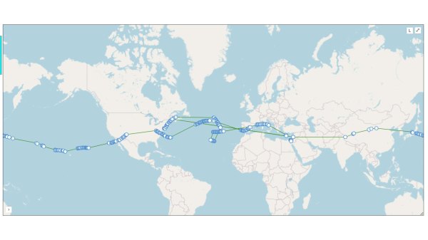
It’s a neat hack that seems to work well: [EngineerGuy314] has launched three prototypes so far, the last of which traveled over 62,000 kilometers/ 38,000 miles.

Emails Over Radio

The modern cellular network is a marvel of technological advancement that we often take for granted now. With 5G service it’s easy to do plenty of things on-the-go that would have been difficult or impossible even with a broadband connection to a home computer two decades ago. But it’s still reliant on being close to cell towers, which isn’t true for all locations. If you’re traveling off-grid and want to communicate with others, this guide to using Winlink can help you send emails using a ham radio.

While there are a number of ways to access the Winlink email service, this guide looks at a compact, low-power setup using a simple VHF/UHF handheld FM radio with a small sound card called a Digirig. The Digirig acts as a modem for the radio, allowing it to listen to digital signals and pass them to the computer to decode. It can also activate the transmitter on the radio and send the data from the computer out over the airwaves. When an email is posted to the Winlink outbox, the software will automatically send it out to any stations in the area set up as a gateway to the email service.

Like the cellular network, the does rely on having an infrastructure of receiving stations that can send the emails out to the Winlink service on the Internet; since VHF and UHF are much more limited in range than HF this specific setup could be a bit limiting unless there are other ham radio operators within a few miles. This guide also uses VARA, a proprietary protocol, whereas the HF bands have an open source protocol called ARDOP that can be used instead. This isn’t the only thing these Digirig modules can be used for in VHF/UHF, though. They can also be used for other digital modes like JS8Call, FT8, and APRS.

Continue reading “Emails Over Radio”

A Spark Gap Transmitter, Characterized

When we think of a spark gap radio transmitter, most of us immediately imagine an early twentieth century ship’s radio room or similar. Most of us know these transmitters as the first radio systems, and from there we’ll probably also know that they were phased out when better circuits arrived, because of their wide bandwidth. So it’s rare in 2024 to find anyone characterizing a spark gap transmitter, as [Baltic Lab] has.

The circuit is simple enough, a high voltage passes through an RC network to a spark gap, the other side of which is a tuned circuit. The RC network and the spark gap form a simple low frequency relaxation oscillator, with the C being charged until the spark gap triggers, forcing the subsequent discharge of the capacitor and causing the spark to extinguish and the cycle to repeat. The resulting chain of high voltage pulses repeatedly energizes the tuned circuit, with each pulse causing a damped oscillation at its resonant frequency. The resulting RF signal is a crude AM tone which can be received fairly simply.

The mathematics behind it all is pretty interesting, revealing both the cause of the bandwidth spread in the low Q factor of the tuned circuit, and the presence of a large spurious frequency spike on an interaction with the capacitor in the RC circuit. It’s all in the video below the break, and we have to admit, it taught us something about radio we didn’t know.

Meanwhile spark gaps weren’t the only early radio transmitter technology. How about an alternator?

Continue reading “A Spark Gap Transmitter, Characterized”

DIY 6 GHZ Pulse Compression Radar

Conceptually, radar is pretty simple: send out a radio wave and time how long it takes to get back via an echo. However, in practice, there are a number of trade-offs to consider. For example, producing a long pulse has more energy and range, but limits how close you can see and also the system’s ability to resolve objects that are close to each other. Pulse compression uses a long transmission that varies in frequency. Reflected waves can be reconstituted to act more like a short pulse since there is information about the exact timing of the reflected energy. [Henrik] didn’t want to make things too easy, so he decided to build a pulse compression radar that operates at 6 GHz.

In all fairness, [Henrik] is no neophyte when it comes to radar. He’s made several more traditional devices using a continuous wave architecture. However, this type of radar is only found in a few restricted applications due to its inherent limitations. The new system can operate in a continuous wave mode, but can also code pulses using arbitrary waveforms.

Some design choices were made to save money. For example, the transmitter and receiver have limited filtering. In addition, the receiver isn’t a superheterodyne but more of a direct conversion receiver. The signal processing is made much easier by using a Zynq FPGA with a dual-core ARM CPU onboard. These were expensive from normal sources but could be had from online Chinese vendors for about $17. The system could boot Linux, although that’s future work, according to [Henrik].

At 6 GHz, everything is harder. Routing the PCB for DDR3 RAM is also tricky, but you can read how it was done in the original post. To say we were impressed with the work would be an understatement. We bet you will be too.

Radar has come a long way since World War II and is in more places than you might guess. We hate to admit it, but we’d be more likely to buy a ready-made radar module if we needed it.

A NanoVNA As A Dip Meter

A staple of the radio amateur’s arsenal of test equipment in previous decades was the dip meter. This was a variable frequency oscillator whose coil would be placed near the circuit to be tested, and which would show an abrupt current dip on a moving coil meter when its frequency matched the resonant frequency of what it was testing. For some reason the extremely useful devices seem hard to come by in 2024, so [Rick’s Ham Shack] has come along with a guide to using a nanoVNA in their place.

It’s a simple enough technique, indeed it’s a basic part of using these instruments, with a large sensor coil connected to the output port and a frequency sweep set up on the VNA. The reactance graph then shows any resonant peaks it finds in the frequency range, something easily demonstrated in the video below the break by putting a 20 meter (14 MHz) trap in the coil and seeing an immediate clear peak.

For many readers this will not be news, but for those who’ve not used a VNA before it’s a quick and easy demo of an immediate use for these extremely versatile instruments. For those of us who received our callsigns long ago it’s nothing short of miraculous that a functional VNA can be picked up at such a reasonable price, and we’d go as far as to suggest that non radio amateurs might find one useful, too. Read our review, if you’re interested.

Continue reading “A NanoVNA As A Dip Meter”

A Long-Range Meshtastic Relay

In the past few years we’ve seen the rise of low-power mesh networking devices for everything from IoT devices, weather stations, and even off-grid communications networks. These radio modules are largely exempt from licensing requirements due to their low power and typically only operate within a very small area. But by borrowing some ideas from the licensed side of amateur radio, [Peter Fairlie] built this Meshtastic repeater which can greatly extend the range of his low-power system.

[Peter] is calling this a “long lines relay” after old AT&T microwave technology, but it is essentially two Heltec modules set up to operate as Meshtastic nodes, where one can operate as a receiver while the other re-transmits the received signal. Each is connected to a log-periodic antenna to greatly increase the range of the repeater along the direction of the antenna. These antennas are highly directional, but they allow [Peter] to connect to Meshtastic networks in the semi-distant city of Toronto which he otherwise wouldn’t be able to hear.

With the two modules connected to the antennas and enclosed in a weatherproof box, the system was mounted on a radio tower allowing a greatly increased range for these low-power devices. If you’re familiar with LoRa but not Meshtastic, it’s become somewhat popular lately for being a straightforward tool for setting up low-power networks for various tasks. [Jonathan Bennett] explored it in much more detail as an emergency communications mode after a tornado hit his home town.

Continue reading “A Long-Range Meshtastic Relay”

A Practical Guide To Understanding How Radios Work

How may radios do you own? Forget the AM/FM, GMRS/FRS radios you listen to or communicate with. We’re talking about the multiple radios and antennas in your phone, your TV, your car, your garage door opener, every computing device you own- you get the idea. It’s doubtful that you can accurately count them even in your own home. But what principles of the electromagnetic spectrum allow radio to work, and how do antenna design, modulation, and mixing affect it? [Michał Zalewski] aka [lcamtuf] aims to inform you with his excellent article Radios, how do they work?

A simple illustration compares a capacitor to a dipole antenna.

For those of you with a penchant for difficult maths, there’s some good old formulae published in the article that’ll help you understand the physics of radio. For the rest of us, there are a plethora of fantastic illustrations showing some of the less obvious principals, such as why a longer diploe is more directional than a shorter dipole.

The article opens with a thought experiment, explaining how two dipole antennas are like capacitors, but then also explains how they are different, and why a 1/4 wave dipole saves the day. Of course it doesn’t stop there. [lcamtuf]’s animations show the action of a sine wave on a 1/4 wave dipole, bringing a nearly imaginary concept right into the real world, helping us visualize one of the most basic concepts of radio.

Now that you’re got a basic understanding of how radios work, why not Listen to Jupiter with your own homebrew receiver?