Editors Note: According to our infallible record keeping, this is the 50,000th post published on Hackaday! We weren’t sure this was the kind of milestone that required any drawn out navel-gazing on our part, but it does seem significant enough to point out. We didn’t pick any specific post to go out in this slot, but the fact that it ended up being a story about the right to repair ice cream machines seems suitably hacky for the occasion.
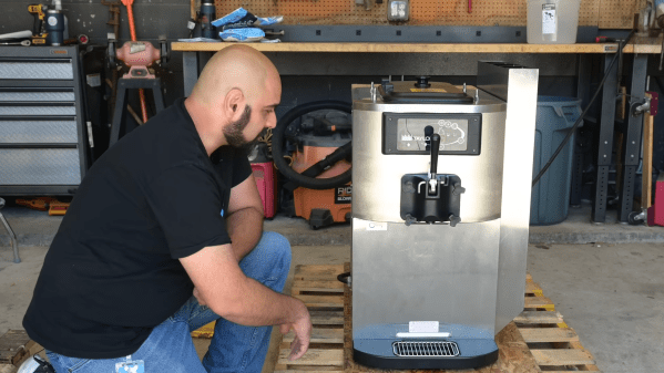
The McDonald’s ice cream machine is one of the great marvels of the modern world. It’s a key part of our heavily-mechanized industrial economy, and it’s also known for breaking down as often as an old Italian automobile. It’s apparently illegal to repair the machines unless you’re doing so with the authority of Taylor, the manufacturer. However, as reported by The Verge, The FTC and DOJ may soon have something to say about that.
Things are coming to a head as the Copyright Office contemplates whether to carve out new exemptions in the Digital Millennium Copyright Act. The legislation is widely reviled by many for making it illegal to circumvent copy protection, an act that is often required to maintain or repair certain equipment. As a result customers are often locked into paying the original manufacturer to fix things for them.
Both the FTC and DOJ have have filed a comment with the Copyright Office on the matter. The language will warm the cockles of your heart if you’re backing the right-to-repair movement.
Changes in technology and the more prevalent use of software have created fresh opportunities for manufacturers to limit Americans’ ability to repair their own products. Manufacturers of software-enabled devices and vehicles frequently use a range of restrictive practices to cut off the ability to do a “DIY” or third-party repair, such as limiting the availability of parts and tools, imposing software “locks,” such as TPMs, on equipment that prevent thirdparty repairers from accessing the product, imposing restrictions on warranties, and using product designs that make independent repairs less available.
The agencies want new exceptions to Section 1201 of the DMCA to allow repair of “industrial and commercial equipment.” That would make it legal to tinker with McDonald’s ice cream machines, whoever you are. The hope is this would occur along with a renewal of exceptions for “computer programs that control devices designed primarily for use by consumers and computer programs that control motorized land vehicles, marine vessels, and mechanized agricultural vehicles.”
Brush up on the finer details of icecreamgate in our previous coverage. This could be a grand time for change. Enough is enough— McDonald’s ice cream machines have been down for too long! Video after the break.
Continue reading “You Should Be Allowed To Fix McDonald’s Ice Cream Machines, Say Federal Regulators” →