An SMD Capacitor Guide

For electronics, your knowledge probably follows a bit of a bell curve over time. When you start out, you know nothing. But you eventually learn a lot. Then you learn enough to be comfortable, and most of us don’t learn as much about new things unless we just happen to need it. Take SMD components. If you are just starting out, you might not know how to find the positive lead of an SMD capacitor. However, if you’ve been doing electronics for a long time, you might not have learned all the nuances of SMD. [Mr SolderFix] has been addressing this with a series of videos covering the basics of different SMD components, and this installment covers capacitors.

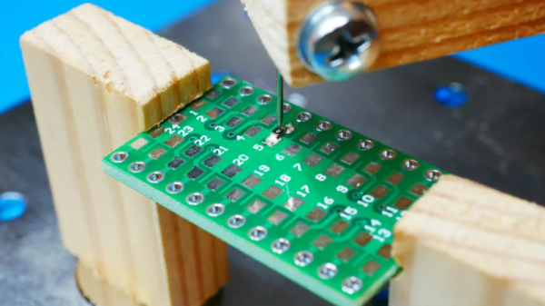
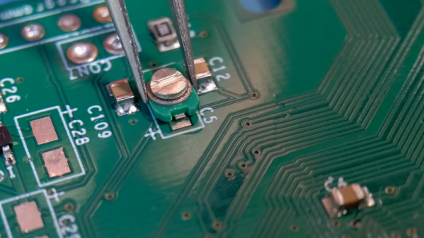
If you are dyed-in-the-wool with SMD, you might not get a lot out of the video, but we picked up a few tips, like using a zip tie for applying flux. The video starts with an examination of the different packages and markings. Then it moves on to soldering the components down.

Continue reading “An SMD Capacitor Guide”

LED Matrix Displays Get New Look Thanks To SMD Stencils

Even if surface-mount skills aren’t in your repertoire, chances are pretty good that most of us are at least familiar with SMD stencils. These paper-thin laser-cut steel sheets are a handy way to apply a schmear of solder paste to the pads of a PCB before component placement and reflowing. But are stencils good for anything else?

It turns out they are, if you’ve got some plain old 8×8 LED matrix displays you want to jazz up a bit. In this case, [upir]’s displays were of the square pixel type, but this trick would work just as well for a matrix with circular elements. Most of the video below is a master class in Adobe Illustrator, which [upir] used to generate the artwork for his stencils. There are a lot of great tips here that make creating one simple shape and copying it over the whole array with the proper spacing a lot easier. He also details panelizing multiple stencils, as well as the workflow from Illustrator to manufacturing.

When lined up properly over the face of the LED matrix, the stencils have quite an effect. We really liked the narrow vertical bars, which make the LED display look a bit like a VFD. And just because [upir] chose to use the same simple shape over all the LEDs in a matrix doesn’t mean that there aren’t other options. We can see how you might use the same technique to create different icons or even alphanumeric characters to create custom LED displays. The possibilities are pretty much limited to your imagination.

This isn’t the first time we’ve seen [upir] teaching old displays new tricks.

Continue reading “LED Matrix Displays Get New Look Thanks To SMD Stencils”

A Homebrew SMD Vise Built From Scrap Wood

We don’t see too many wooden projects around these parts, but when [olikraus] turned a few pieces of scrap lumber into a functional SMD vise, how could we not take notice? The idea is simple. Two pieces of wood with slots in them hold the PCB. Two other pieces form an arm with an adjustable needle that can hold down tiny parts while you solder. Magnets hold each piece to a metal working surface. Simple and elegant.

We might have 3D printed some of the pieces, but then again, you have to be careful where your soldering iron goes if you go that route. The other advantage to using wood is that you can easily grab a few pieces of scrap and have a different-sized vice in just a few minutes.

There are a few improvements we might suggest. For example, a thumbscrew to fix the needle would be welcome. It seems like you could make the part that holds the needle smaller, too, to help you get your soldering iron into the same area. But it looks workable with no changes at all.

Working with scrap wood isn’t glamorous, but it does make for quick and easy functional builds. A number of the holes and bolts here could even be replaced with glue if you don’t mind the time for it to set.

Of course, you could mix and match this with other designs. We like the “dollar store PCB holder,” but it would work well with the arm from this project. We couldn’t help but think of the SMD beak when we saw this project.

Automate Parts Kitting With This Innovative SMD Tape Slicer

Nobody likes a tedious manual job prone to repetitive stress injury, and such tasks rightly inspire an automated solution. This automatic SMD tape cutter is a good example of automating such a chore, while leaving plenty of room for further development.

We’re used to seeing such tactical automation projects from [Mr Innovative], each of which centers on an oddly specific task. In this case, the task involves cutting a strip containing a specific number of SMD resistors from a reel, perhaps for assembling kits of parts. The mechanism is simple: a stepper motor with a rubber friction wheel to drive the tape, and a nasty-looking guillotine to cut the tape. The cutter is particularly interesting, using as it does a short length of linear bearing to carry a holder for a razor blade that’s mounted perpendicular to the SMD tape. The holder is mounted to a small motor via a crank, and when the proper number of parts have been fed out, the motor rotates one revolution, driving the angled blade quickly down and then back up. This results in a shearing cut rather than the clipping action seen in this automated wire cutter, also by [Mr Innovative].

Curiously, there seems to be no feedback mechanism to actually measure how many resistors have been dispensed. We assume [Mr Innovative] is just counting steps, but it seems easy enough to integrate a photosensor to count the number of drive sprocket holes in the tape. It also seems like a few simple changes would allow this machine to accommodate SMD tapes of different sizes, making it generally useful for SMD kitting. It’s still pretty cool as a tactical project, though, and does a great job inspiring future improvements.

Continue reading “Automate Parts Kitting With This Innovative SMD Tape Slicer”

Label Your SMD Tapes With An Inkjet Printer

If you’ve ever had to use SMD components on tape outside the realm of the automated assembly machines for which they were designed, you’ll know that one tape looks very like another and it can be very annoying to keep track of which is which. We can’t help admiring [Yvo de Haas’] inkjet printer for SMD tapes then, which efficiently prints whatever identifying marks you need on the back of your tapes.

The printer uses the venerable HP45 inkjet cartridge, and teams it with a 3D printed mechanism and [Yvo]’s self-designed driver board. A worm gear motor and a sprocket take care of advancing the tape through the mechanism past the printhead, and there is a well-assembled piece of software to drive it all. With extremely comprehensive build instructions it should be within the reach of anyone who handles component tape, and from our experience of hand-labeling tape for kits we can see that it could be a Godsend. Take a look at it in action in the video below.

So far the tape-handling machinery we’ve seen has mostly been for cutting sections rather than labeling. We can see that this printer paired with a tape cutter should be essential equipment for anyone starting a kit business.

Continue reading “Label Your SMD Tapes With An Inkjet Printer”

Streamline Your SMD Assembly Process With 3D-Printed Jigs

Your brand-new PCBs just showed up, and this time you even remembered to order a stencil. You lay the stencil on one of the boards, hold it down with one hand, and use the other to wipe some solder paste across…. and the stencil shifts, making a mess and smearing paste across the board. Wash, rinse (with some IPA, of course), repeat, and hope it’ll work better on the next try.

openscad window
A PCB jig generated by OpenSCAD

Maybe it’s time to try Stencilframer, a 3D-printable jig generator created by [Igor]. This incredibly useful tool takes either a set of gerbers or a KiCad PCB file and generates 3D models of a jig and a frame to securely hold the board and associated stencil. The tool itself is a Python script that uses OpenSCAD for all 3D geometry generation. From there, it’s a simple matter to throw the jig and frame models on a 3D printer and voilà!– perfectly-aligned stencils, every time.

This is a seriously brilliant script. Anyone whose gone through the frustration of trying to align a stencil by hand should be jumping at the opportunity to try this out on their next build. It could even be paired with an Open Reflow hot plate for a fully open-source PCB assembly workflow.

Continue reading “Streamline Your SMD Assembly Process With 3D-Printed Jigs”

Decoding SMD Part Markings

You’ve probably encountered this before — you have a circuit board that is poorly documented, and want to know the part number of a tiny SMD chip. Retro computer enthusiast [JohnK] recently tweeted about one such database that he recently found, entitled The Ultimate SMD Marking Codes Database. This data base is only a couple of years old judging from the Wayback Machine, but seems to be fairly exhaustive and can be found referenced in quite a few electronics forums.

Unlike their larger SMD siblings, these chips in question are so small that there is no room to print the entire part number on the device. Instead, the standard practice is for manufacturers use an abbreviated code of just a few characters. These codes are only unique to each part or package, and aren’t necessarily unique across an entire product line. And just because it is standard practice does not imply the marking codes themselves follow any standard whatsoever. This seemingly hodgepodge system works just fine for the development, procurement and manufacturing phases of a product’s lifecycle. It’s during the repair, refurbishment, or just hacking for fun phases where these codes can leave you scratching your head.

Several sites like the one [JohnK] found have been around for years, and adding yet another database to your toolbox is a good thing. But none of them will ever be exhaustive. There’s a good reason for that — maintaining such a database would be a herculean task. Just finding the part marking information for a known chip can be difficult. Some manufacturers put it clearly in the data sheet, and some refer you to other documentation which may or may not be readily available. And some manufacturers ask you to contact them for this information — presumably because it is dynamic changes from time to time. Continue reading “Decoding SMD Part Markings”