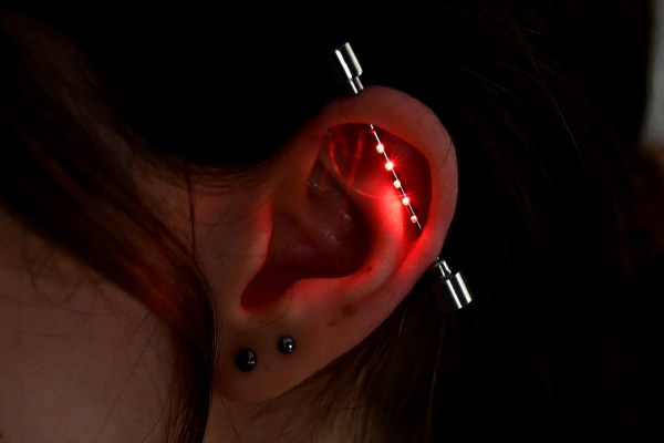
We’ve covered [mitxela] in the past and if you know him, you’ll likely know him for putting the micro in microelectronics. This year, he’s at it again with his LED Industrial Piercing.
This tiny PCB is really pushing the limits of fabrication
Inspired by the absolutely tiny 0402 LEDs and industrial piercings, [mitxela] started thinking of a way to construct the 5cm long device. He found some normal LED earrings to steal the battery compartment from. Then, with a tick needle and some more steel, he created a new industrial earring with some holes.
Of course, no [mitxela] project is complete without comically tiny microsoldering and this project makes the VQFN ATTiny he used look large. He puts his PCB suppliers to the test with a merely 1mm wide flex PCB for the LEDs to be mounted on. Finally, he combines the flex PCB, the earring and some epoxy to create yet another piece of LED jewelry.
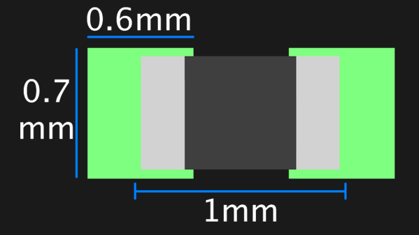
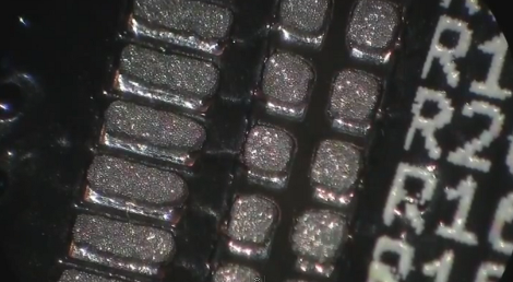
Assembling with a stencil is just that much more convenient – it’s a huge timesaver, and your components no longer need to be individually touched with a soldering iron for as many times as they have pads. Plus, it usually goes silky smooth, the process is a joy to witness, and the PCB looks fantastic afterwards! However, sometimes components won’t magically snap into place, and each mis-aligned resistor on a freshly assembled board means extra time spent reflowing the component manually, as well as potential for silent failures later on. In an effort to get the overall failure rate down, you will find yourself tweaking seemingly insignificant parameters, and [Worthington Assembly] proposes that you reconsider your 0402 and 0201 footprints.
Over the years, they noticed a difference in failure rates between resistor&capacitor footprints on various boards coming in for assembly – the size and positioning of the footprint pads turned out to be quite significant in reducing failure rate, even on a tenth of millimeter scale. Eagle CAD default footprints in particular were a problem, while a particular kind of footprint never gave them grief – and that’s the one they recommend we use. Seeing the blog post become popular, they decided to share their observations on 0201 as well, and a footprint recommendation too. Are your 0402 resistors giving you grief? Perhaps, checking the footprints you’re using is a good first step.
The 0402 and 0201 components are in a weird spot, where soldering iron assembly is no longer really viable, but the stencil+reflow approach might not be unilaterally successful when you start off – fortunately, that’s where writeups like these come in. Interested in learning stenciling? Get some solder paste, and read up on all the different ways you can put it onto your boards.
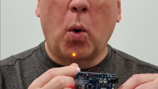
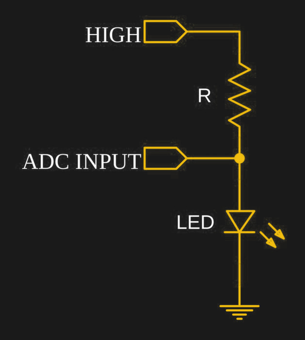
We’d seen it done with buttons, switches, gestures, capacitive touch, and IR remote, but never like this. [electron_plumber] made an LED that can be blown out like a candle, and amazingly it requires no added sensors. The project uses an Arduino to demonstrate turning a tiny LED on and off in response to being blown on, and the only components are the LED and a resistor.
[electron_plumber] used an 0402 LED and thin wires to maximize the temperature responses.How is this done? [electron_plumber] uses an interesting property of diodes (which are the “D” in LED) to use the LED itself as a temperature sensor. A diode’s voltage drop depends on two things: the current that is being driven through the diode, and the temperature. If the current is held constant, then the forward voltage drop changes reliably in response to temperature. Turning the LED on warms it up and blowing on it cools it off, causing measurable changes in the voltage drop across the device. The change isn’t much — only a handful of millivolts — but the effect is consistent and can be measured. This is a principle [Elliot Williams] recently covered in depth: using diodes as temperature sensors.
It’s a clever demo with a two important details to make it work. The first is the LED itself; [electron_plumber] uses a tiny 0402 LED that is mounted on two wires in order to maximize the temperature change caused by blowing on it. The second is the method for detecting changes of only a few millivolts more reliably. By oversampling the Arduino’s ADC, an effectively higher resolution is obtained without adding any hardware or altering the voltage reference. Instead of reading the ADC once, the code reads the ADC 256 times and sums the readings. By working with the larger number, cumulative changes that would not register reliably on a single read can be captured and acted upon. More details are available from [electron_plumber]’s GitHub repository for LEDs as Sensors.
Embedded below is a video that is as wonderful as it is brief. It demonstrates the project in action, takes a “show, don’t tell” approach, and is no longer than it needs to be.
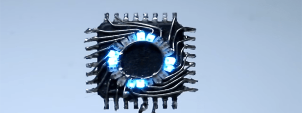
Using nothing more than some solder, wire, 20 x Pico 0402 (1mm x 0.5mm) blue LEDs and an ATmega328P (7mm x 7mm), [The Tweaker] managed to cram 20 LEDs into a circle on the top of the chip soldered in dead bug style. The chip is running some Arduino code and is operating on the 8 MHz internal crystal oscillator, so that manages to keep the part count low. The soldering is done in a spiral so the LED terminals are hooked up to the right pins, but it seems to add to the aesthetics of the project and looks like it would take a really steady hand. Once you connect a power source it displays chasing lights as well as other light patterns.
There may not be much to this project but it does look great.
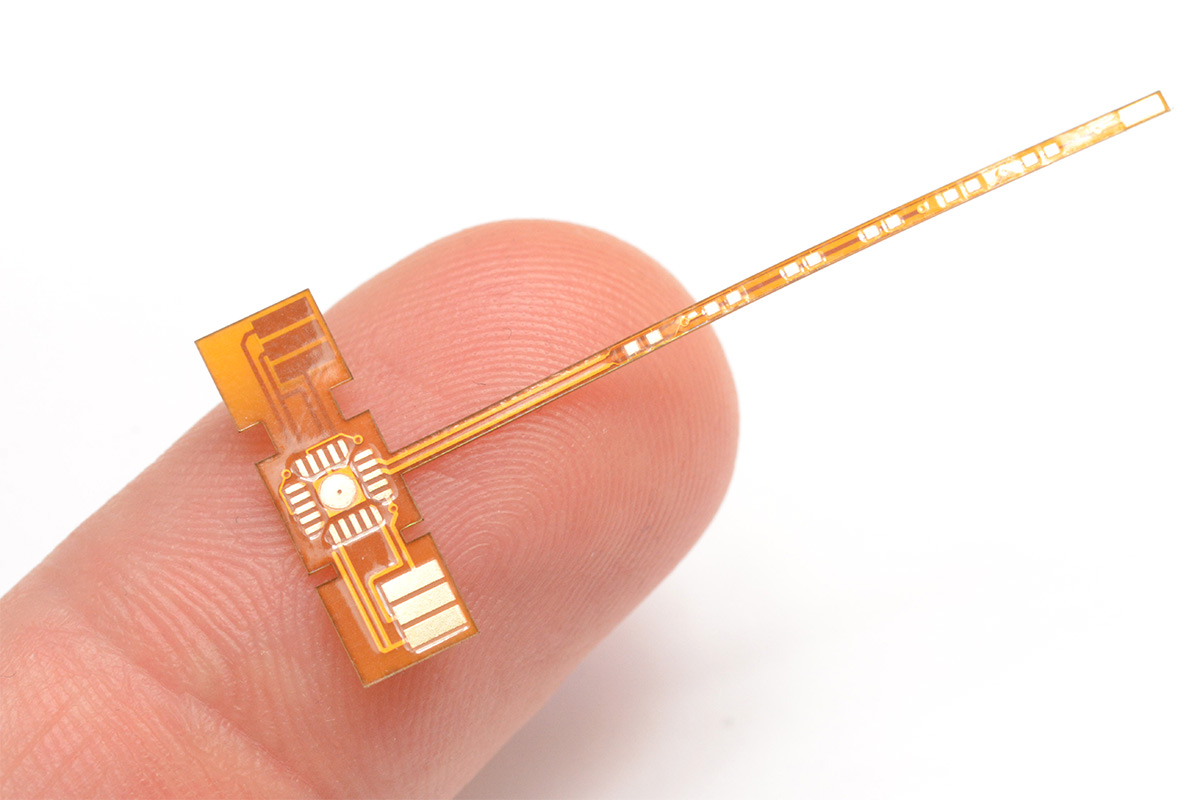
Using FTDI chips as a USB to Serial solution is nothing new, but this MicroFTX board takes the footprint to a new low. If you’re space limited this should have no problem fitting into your project. But if you plan to use it for prototyping we predict it’ll be lost in the parts bin forever as soon as you take your eyes off of it.
The USB Mini-B connector is becoming quite popular with hobby electronics these days. But here [Jim Paris] chose to use its little brother, the USB micro connector. Want to put this together by hand? How are you with 0402 footprints and QFN chips? In fact, there’s a ground pad on the bottom of that IC which means you really need to use a reflow oven to do the job right.
Aside from the diy-unfriendly fabrication size, we do like the design. There are four output pins (voltage, ground, TX, and RX) with a set of four solder jumpers to configure them. It can be powered from the USB port or an external connection, with the option for 5V or 3.3V output.
We try to stick to the 0805 parts because they’re still big enough to solder by hand. But [Scott] shows us that it doesn’t take too many special tools to reflow fine-pitch components at home. In this case he’s using 0402 resistors, a footprint that we consider functionally impossible to solder using an iron.
The two parts of the equation that he spent some money on are professionally produced PCBs and a solder stencil. The stencil is laser-cut from Kapton, which is heat-resistant so it doesn’t warp during the cutting process. An acrylic frame holds the PCB in place, and he just tapes the stencil over it and uses a chunk of acrylic as a squeegee to evenly apply the solder paste. Splurging on the PCB and stencil means you’ll achieve tolerances which lead to success.
The next issue is placing the components. [Scott] shows off some vacuum tweezers he built using an aquarium pump. Watch the video after the break to see how small those 0402 parts are when he extracts one of the resistors from the tape packaging. With the board manually populated (check everything twice!) he moves the board to a completely unaltered toaster oven for reflow. We have seen a lot of projects which add controllers to these ovens, but he really makes the case that you don’t need it. Instead, he uses a thermocoupler read by a multimeter just to let him know what’s going on with the temperature. He uses a smart phone as a timer, and switches the oven on and off to match the solder’s heat profile. Continue reading “Fine-pitch SMD Soldering With Minimal Tools”→