Barebones PIC RFID Tag

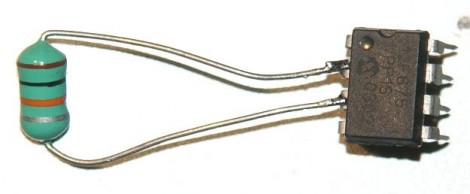
An inductor and 8-pin microcontroller are all that make up this barebones RFID tag. You might have done a double-take when first seeing the image above. After all, there’s nothing hooked up to the power and ground pins on the chip. As [Ramiro Pareja] explains in his post, the power is actually supplied via the I/O pins to which the inductor is soldered. It seems that each I/O pin has a parasite capacitor and a pair of clamping diodes inside the chip. When the AC current that is induced by the magnetic field of the RFID reader hits those pins, the capacitors charge and the clamping diodes form a bridge rectifier. This results in power being injected into the chip, which turns around and sends the RFID code back through the inductor.

This isn’t the first time that we’ve seen this concept. We featured a hack that is exactly the same except it used an AVR chip. This one uses a PIC 12F683 but should work with just about any 12F or 16F model. The code is written in Assembly and shouldn’t need any changes for different hardware. [Ramiro] does talk a bit about adding a decoupling capacitor to Vss and Vdd, as well as a tuning capacitor to the two I/O pins used above to help make the device a little more robust. But, as you can see in the video after the break, it works just fine without them.

Continue reading “Barebones PIC RFID Tag”

HsNet: Node Communications For Feature-limited Microcontrollers

[Diego Spinola] wrote in to tell us about a node communication system he’s been working on called HsNet. The aim is to build a system of nodes that can be made up of small and inexpensive microcontrollers. The problem is that the least expensive controllers often don’t have a hardware UART. HsNet implements the RS485 protocol using a software UART along with a slim and sleek addressing scheme.

The first module developed, seen in the image above and video after the break, is a single channel pulse-width-modulation node using a PIC 12F683. It can be sent commands in the payload of the HsNet packet format. The PWM modules accept three different commands; one is a desired PWM value, another is a delay between steps for the PWM, and the last toggles a blink function.

He has also developed an analog sensor module and an Arduino-based TCP/IC gateway module. Now that the packet communications have been established, it will be rather simple to add nodes based on that groundwork. [Diego] brought these components together to build an interactive wall which can also be seen after the break.

Continue reading “HsNet: Node Communications For Feature-limited Microcontrollers”

Multitool Alarm System

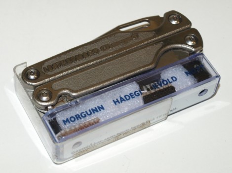
Here’s a way to make sure you don’t leave your Leatherman multitool somewhere. It’s an alarm system that will start a timer when the tool is removed from the holster. After five minutes the module beeps to remind you to put the tool back where it belongs. Annoying? Possibly, but if you’re not done with your work just press the reed leaf switch on the module to reset the timer. A PIC 12F683 handles the timing and generates the waveform for the piezo buzzer. Perhaps this could have been accomplished with a dual 555 chip like the LM556 (one timer for the countdown and another for the piezo waveform) but the PIC has power-down modes available that should make the button batteries last a long time.

Driving An 8-digit Split Flap Display

[Markus] got his hands on a split-flap display and built a controller for it. These sometimes can be found on really old alarm clocks, but [Markus] was a lucky-duck and managed to acquire this large 8-digit display which previously made its home in a railroad station. They work like a Rolodex, mounting flaps around a cylinder for a full alpha-numeric font set.

A PIC 12F683 was selected to control the display, using optoisolation to separate the 42V display motors from the driver circuit. From the video after the break we think he did a wonderful job of getting this working. It only takes six I/O pins to control and the sound and look of the digits scrolling leaves us quite jealous.

So what’s he got in store for it? The first thing he did was use it to count down to the New Year.

Continue reading “Driving An 8-digit Split Flap Display”

Halloween Props: Dancing Spider

[Isaac] grabbed the motor from an old printer and used it to make a spider run up and down the wall for Halloween. A PIC 12F683 uses a MOSFET to drive the motor. The program loop has a little bit of dramatic flare to it, raising the arachnid with a bit of a jerky motion to give it some life, then wait for a time before quietly lowering the spider (hopefully onto an unsuspecting party-goer).  The driver board is set up for two motors, making it easy to reuse in future projects. This is quite effective, and the only addition we might suggest is to add a couple of red LEDs as some glowing eyes.

Take a look at the finished product after the break.

Continue reading “Halloween Props: Dancing Spider”