If you’ve ever spent any time around a lab, you’ve doubtless seen one of those awesome combination magnetic stirrer and heater plates that scientists use to get liquids mixed and up to temperature. If you’ve ever etched your own PCBs using ammonium persulfate, you’ve experienced the need for both heating and agitation firsthand. Using a stirrer plate for PCB etching is putting two and two together and coming up with four. Which is to say, it’s a good idea that’s not amazingly novel. [acidbourbon] built his own, though, and there’s almost no part of this DIY heater/stirrer that isn’t a hack of some kind or another.
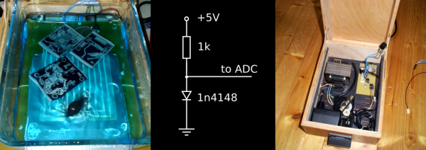
Start off with the temperature controller. Instead of buying a thermocouple or using an LM75 or similar temperature-measurement IC, [acidbourbon] uses a bog-standard 1n4148 diode. The current passed through a diode, at a given voltage, is temperature dependent, which means that adding a resistor and a microcontroller’s ADC yields a quick hacked temperature sensor. [acidbourbon] glued his straight onto the casserole that he uses as an etching tray.
Does the type of person who saves $0.25 by using a diode instead of a temperature sensor go out and buy a stirrer motor? No way. Motor and gears come from a CD-ROM drive. The “fish” — the magnetic bar that spins in the etchant — is made of neodymium magnets lengthened by shrink-wrapping heat-shrinking them together with some capacitors. Who knew that shrinkwrap heat-shrink, fused with pliers, was waterproof? Is that a wall-wart in that box, with the prongs wired to mains electricity?
Anyway, this just goes to show that etching equipment need not be expensive or fancy. And the project also provides a showcase for a bevy of tiny little hacks. And speaking of [acidbourbon]’s projects, this semi-automatic drill press mod has been on our to-do list for two years now. Shame on us! Continue reading “Magnetic Stir Plate Is A Hack”


