Prototyping A Low-resolution Handheld Gaming Rig

low-res-arduino-gaming

[Jason] has been hard at work on this Arduino-based low-res gaming platform. He even had a fab house deliver circuit boards to pull everything together. It’s a little small in his hands, and the graphics are limited to the 8×8 pixels provided by the display. But it still looks like a lot of fun and the code was written to make adding new games quite painless.

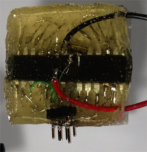
The board hosts an ATmega328 which drives the bi-color LED display using a pair of TPIC6B595 shift registers. Control is provided by a collection of buttons to either side of the display. The unit is powered by three AAA batteries held in a pack soldered to the back side of the PCB.

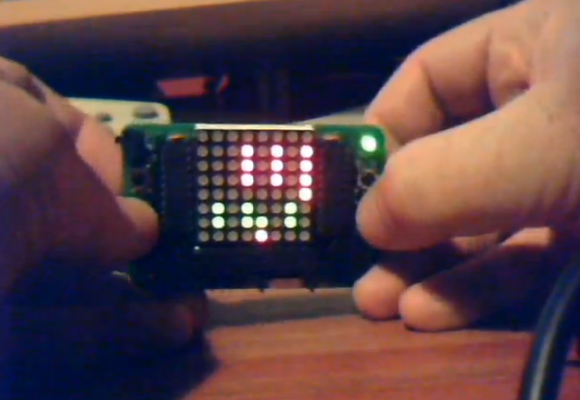
The image above shows [Jason] giving a Space Invaders game a try. The clip after the break shows respectable action, sound from a piezo buzzer, and it even scrolls your score at the end of the game. But you’re not limited to just one title. Adding new games is as easy as implementing a class in a new header file. You can get a feel for how this is set up by viewing the source code repo.

This reminds us of the Pixel Bros low-res system.

Continue reading “Prototyping A Low-resolution Handheld Gaming Rig”

8×8 LED Matrix Pendant Sealed In A Block Of Epoxy

8x8-led-pendant

This is the back side of [Dmitry Grinberg’s] 8×8 LED matrix pendant. He had seen the other projects that used a 5×7 grid but wasn’t really satisfied with the figures that can be drawn in that confined area when each pixel has only the option of being on or off. His offering increases the drawing area and includes the ability to display each pixel at several different levels.

He’s using an ATmega328 microcontroller soldered directly to the pins on the back of the LED module. He mapped out the IO in his firmware to make the soldering as easy as possible. To protect the hardware he fashioned a mold around the edges of the LED package using duct tape. The tape held epoxy in place as it hardened, encasing the microcontroller and holding the power wires and ICSP header tightly.

After the break you can see about six seconds of the device in action. The four levels of brightness for each pixel really do make quite a difference!

Continue reading “8×8 LED Matrix Pendant Sealed In A Block Of Epoxy”

Matrix Backpack Was A Fun Design Project

[Greg] is really working on a small scale with his LED Matrix backpack PCB. It’s a toy that he designed as an activity. He constrained himself to a board which would exactly match the outline of an 8×8 bicolor LED matrix package.

What you see here is the side of the PCB which will be facing the underside of the LED dot matrix module. Let’s call this the top of the board. The underside has a CR2032 battery holder which provides enough juice to run the display. Since the matrix is bi-color there’s a slew of pins to drive. [Greg] uses three shift registers for the high side, and sixteen N-channel MOSFETS for the low side. He’s chosen an MSP430G2201 microcontroller which has a nice sleep mode for power conservation. It has no problem driving tri-color animations as seen the clip after the break, but also has an unpopulated clock crystal footprint if you wanted to use it as a timepiece.

Despite the small footprints and cramped board [Greg] still hand soldered all of the components. He even posted a time-lapse of the process in the page linked at the top.

Continue reading “Matrix Backpack Was A Fun Design Project”

Xbee Remote Sensors Tell You When Someone Enters Your Home

[Bill Porter] is helping a friend out by designing a simple security system for her home. It relies on Xbee modules to alert a base station when doors are opened, or a pressure mat is stepped on.

The door sensors are quite simple, and you’re probably already familiar with them. One part mounts to the door and has a magnet in it, the mating part mounts to the jamb and has a reed switch that closes a contact when the magnet is in place. The floor mat uses two sheets of conductive material separated by bits of foam. When it is stepped on a circuit is completed and can be sensed by the Xbee as a button press.

These sensors report back to an Arduino base station that has a buzzer and three 8×8 LED modules to scroll a message saying which sensor was tripped. [Bill] does a good job of showing what goes into configuring an Xbee network if you’ve never worked with the hardware before.

You’ll find his demo video after the break.

Continue reading “Xbee Remote Sensors Tell You When Someone Enters Your Home”

Super Pixel Bros Now With Manufactured PCB And Rewritten Software

[Retro Brad] has come a long way with his 8×8 gaming device which he calls Super Pixel Bros. The newest rendition has a fab house PCB and freshly rewritten code. The game is still played on an 8×8 LED matrix, but it looks like he’s sourced a version with square pixels, which is a nice touch since he was inspired by the block-based Super Mario games. Also new in this version is the character LCD screen which displays score, level, and life information. But it’s not just the shiny new hardware that’s different, he’s rewritten the software in Swordfish Basic to run on the PIC 18F4550. The new code allowed him to tweak how levels are loaded and stored. He’s even written a level editor and has finished 20 levels thus far.

The demo after the break does a great job of showing off the hardware and the game play. He’s added a lot, including enemies, the ability to shoot fire, and of course the common moves of jumping and breaking blocks is all there. He mentioned that the fab house he used is selling boards for around $5 and he’s looking into the possibility of getting a kit service up and running.

His progress since we last checked in on the project is quite impressive.

Continue reading “Super Pixel Bros Now With Manufactured PCB And Rewritten Software”

Bi-color LED Matrix Clock Uses Point-to-point Construction

[Daniel] wanted his child to stay in bed until a semi-decent time each morning. The problem is the kid doesn’t know how to read a clock, so [Daniel] built him a clock. Yeah, doesn’t make much sense to us either, but we’ve used our own shaky premises for projects so who are we do judge?

He used a bi-color 8×8 LED matrix as the clock display. What caught our eye is the point-to-point soldering he used for the three strip boards that make up the device. Note the use of a drill-bit to break the traces when needed. Each board has its own purpose; the matrix drive, the logic board, and the power board. A PIC 18F4550 lets [Daniel] control the clock via USB, and takes care of lighting up the hour as a red number when it’s time to sleep, and a green one when it’s okay to arise. There’s a flashing pixel for seconds, and a binary readout of minutes along the bottom.

We’ve asked [Daniel] to post a schematic and an image of the clock face when displaying the time. No word yet but we’ll keep our eye on it. In the mean-time, check out this clock that uses an RGB 8×8 LED matrix.

Build A Pong Gaming Console

A lot of thought went into [Patrick Mccabe’s] Pong gaming console build. He used components we’re familiar with; an Arduino as a controller, 8×8 LED modules as the display, and potentiometers (with fancy knobs) in project boxes as the controllers. But every step along the way he took care to build this cleanly and robustly. Even the MAX7219CNG drivers for the six LED modules reside on PCBs from a fab house. The finished project is something you’d be proud to pull out and play when you have friends over. Even if they’re not part of the geek elite we think they’d enjoy a game or two. Great job [Patrick]. We hope to see an internalized microcontroller and scoring in your next update!

Want to do this but the cost of the matrix drivers scared you away? Follow our tutorial to build your own display using an AVR for the multiplexing.