Fail Of The Week: Inaugural Edition

We’re sure you’ve all been waiting on the edge of your seats to see whose project makes it as the first Hackaday Fail of the Week. Wait no longer, it’s [Mobile Will] with his woeful tale about monitoring AC current usage.

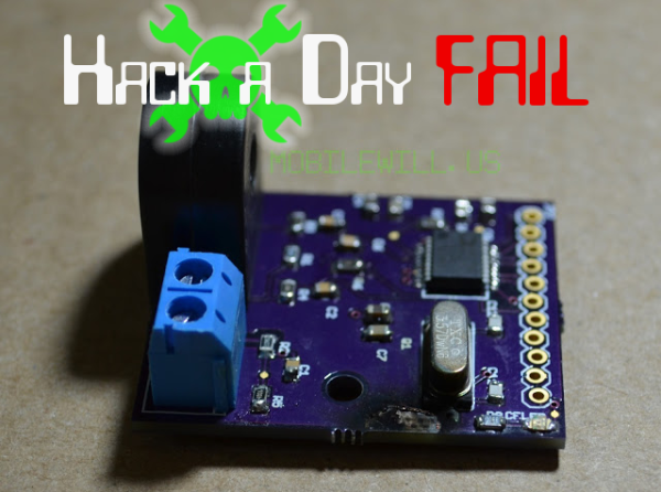
He had been working on a microcontroller actuated mains outlet project and wanted an accurate way to measure the AC current being used by the device connected to it. The ADE7753 energy metering IC was perfect for this so he designed the board above and ordered it up from OSH Park. After populating the components he hooked it up to his Arduino for a test run, and poof! Magic blue smoke arose from the board. As you’ve probably guessed — this also fried the Arduino, actually melting the plastic housing of the jumper wire that carried the rampant current. Thanks to the designers of the USB portion of his motherboard he didn’t lose the computer to as the current protection kicked in, requiring a reboot to reset it.

We can’t wait to hear the conversation in the comments. But as this is our first FotW post we’d like to remind you: [Mobile Will] already knows he screwed up, so no ripping on his skills or other non-productive dibble. Let’s keep this conversation productive, like what caused this? He still isn’t completely sure and that would be useful information for designing future iterations. Update: here’s the schematic and board artwork.

We’ve got a bit more to share in this post so keep reading after the break.

Continue reading “Fail Of The Week: Inaugural Edition”

Simple Power Adapter Thumbs Its Nose At Proprietary Connectors

[Mike Worth] wanted to use his camera for some time-lapse photography. Since it’s used to take many pictures over a long period of time, he doesn’t want to deal with batteries running low. But there’s no standard power jack on the side; instead the official charger consists of an adapter that is inserted in place of the batteries. Rather than break the bank with the special cable, [Mike] made his own battery compartment A/C adapter.

You can see that it is made up of two parts. The first is a standard wall wart that outputs the correct voltage and has an acceptable current rating. The other part is the adapter cable that connects to the camera on one end, and has a barrel jack on the other. [Mike] rolled some paperboard around a pencil until it matched the diameter of a AA battery. Once of the cylinders has a thumb tack for the negative lead, and the other uses a screw and washer for the positive side. He soldered some wire to these and he’s in business.

He must be snapping photos frequently enough to avoid the auto-shutoff feature. That or he’s disabled it with the use of some custom firmware.

Rebuilding A Fried Fan Motor

The fan motor on [Pete’s] oscillating tower fan conked out on him. It’s a shame to throw away the whole thing, but it’s near impossible to source parts for a small appliance like this one. So he set out to rebuilt the motor and get the thing working like new.

The motor in question is of the brushless AC variety. [Pete’s] gut told him that the failure was due to bad lubrication of the bearings at the factory. It stopped working because the commutator could no longer rotate freely. A check of the continuity of each of the coils led him to this thermal fuse. When the motor seized the AC current built up a lot of heat. This fuse is made to burn out before a fire can start but now it needs to be replaced. With a new one in place he reassembled the motor, making sure to pack the bearings with some quality lubricant. Now he’s once again ready for a long hot summer.

Wireless IPod Charger Built From Scratch

Despite the obvious use of a lot of wire, this project is actually a wireless charging system. [Jared] built it as a way to explore the concepts behind transferring power inductively. Alternating current on one of the white coils induces current on the other. This is then rectified, and regulated for use as a 5V charger. In this case it powers his iPod, but any USB device should work with the setup.

The transmitter uses the power supply from an old laptop as a source. Some filtering and a couple of MOSFETS are responsible for generating the AC current on the transmitting coil. The receiving coil feeds the bridge rectifier. In the writeup that voltage is fed to a 7805 regulator to provide a stable 5V output. However, in the video demo after the break [Jared] shows off the boost converter that he uses on his improved circuit. This way if the voltage drops due to poor alignment of the coils it will still be able to provide a steady output.

We’ve seen the same coil concept used to add wireless charging to cellphones too.

Continue reading “Wireless IPod Charger Built From Scratch”

Hacking An AC Outlet Timer For Project Use

[Karl] needed a programmable real-time clock for one of his projects. He considered adding an RTC chip, LCD screen, and some buttons for use with a microcontroller. That’s not necessarily hard, but it takes time and can be considered a project in itself. Instead, he headed to the hardware store to look for a cheap solution. He was able to get this AC outlet timer for a song. It’s got everything he needs; twenty programmable on/off events, a calendar to track time and day of week, and a user interface made up of a low-power LCD and four buttons. He cracked open the case and patched into the electronics for use with any project.

You can see the solder-tab battery in the middle of the board (green coin-cell). That actually runs the timer circuitry and display. It’s topped off when the unit is plugged into mains, but [Karl] ended up replacing it with a much higher capacity AA rechargeable battery. The device works just like a thermostat, using very little power and driving a relay at the appropriate time. Batteries in thermostats seem to last forever and we can expect the same performance from this device. [Karl] rerouted the trigger signal from the relay to his own 2N2222 transistor. This way the device can switch loads running at voltages other than its own 1.2V operating level.

Stock timers are great. They’re mass-produced which makes them cheap, and you can do some interesting stuff with them. We really enjoyed see this other mechanical version hacked for hydroponic use.

Dimming AC Lights The Hard Way

It’s that time of year again where the thermometer drops, the sun sets earlier, and we try to warm our hearts with the solstice festival that is common in our own respective cultures. Of course we all need a few strings of lights, but wouldn’t it be great if we had PWM controlled dimmable lights?

When he started out on his PWM-controlled, AC-powered light box, [Waterbury] immediately realized that relays were not going to be an optimal solution. The best way out of the mess he dug himself into would be via zero crossing. After getting a transformer wired up to a transistor for the detection circuit, a short bit of code was written in the wee hours of the morning and a proof of concept was had.

With the control box complete, [Waterbury] hacked up a quick VB app and piped the output of a WinAmp visualizer into the lights via serial. The Inception demo was great, but finer-grain control was needed. After seeing a Hack a Day post on a nice equalizer chip, the seven band output on IC were converted to UART.

[Waterbury] took his seven-band AC-controlled light box to a Halloween party with his synth and the results looked awesome. You can check that out after the break, but we’re really waiting to see his Christmas decorations this year.

Continue reading “Dimming AC Lights The Hard Way”

Experimenting With Bridge Rectifers For AC To DC Power Conversion

The folks over at Toymaker Television have put together another episode. This time they’re looking at bridge rectifiers and how they’re used in AC to DC converters.

This is a simple concept which is worth taking the time to study for those unfamiliar with it. Since Alternating Current is made up of cycles of positive and negative signals it must be converted before use in Direct Current circuits; a process called rectification. This is done using a series of 1-way gates (diodes) in a layout called a bridge rectifier. That’s the diamond shape seen in the diagram above.

This episode, which is embedded after the break, takes a good long look at the concept. One of the things we like best about the presentation is that the hosts of the show talk about actual electron flow. This is always a quagmire with those new to electronics, as schematics portray flow from positive to negative, but electron theory suggests that actual electron flow is the exact opposite. Continue reading “Experimenting With Bridge Rectifers For AC To DC Power Conversion”