FM 101 And Transmitter Build With Afroman

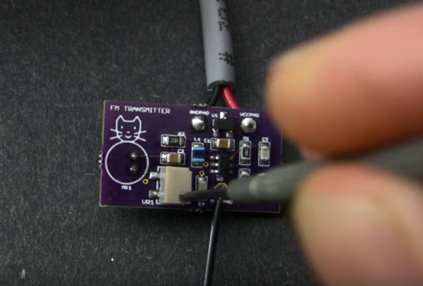
One of our favorite purveyors of electronics knowledge is at it again. This time, [Afroman] explains how frequency modulation works while building up a short-range FM transmitter on a board he has available at OSH Park.

The design is based on a MAX2606 voltage-controlled oscillator (VCO) chip that can do 70-150MHz. [Afroman] sets it up to oscillate at about 100MHz using a 390nH inductor. He also put a potentiometer voltage divider on the 2606’s tuning pin. Voltage changes issued through the pot alter the transmitting frequency in small increments, making it easy to dial in a suitable channel for your broadcast. Add an electret mic and about a meter’s worth of solid-core wire and you have yourself an FM transmitter that is good for around 20 meters.

There are plenty of ways to build a small FM transmitter that allow for some experimentation and don’t involve placing SMD components. We covered a build last summer that uses a couple of 3904s and rides a 9V connector salvaged from a dead battery. The downside is that transistor-based transmitters tend to be less frequency-stable than a VCO chip.

Continue reading “FM 101 And Transmitter Build With Afroman”

An Introduction To Zener Diodes

[Afroman] is back again with another great tutorial video on the basics of electronics. This time it’s zener diodes.

Page three or four of every ‘beginners guide to electronics’ covers a diode as, “a component that only allows current to flow in one direction.” This is true; a diode only allows current to flow in one direction. However, like any depth of knowledge, the dialectic of diodes quickly turns to a series of, ‘but..’ and ‘however…’ statements.

A zener diode is like a normal silicon diode, where a forward biased diode will pass current with a ~1 volt drop. When a zener diode is reversed biased, there’s a different voltage drop, annotated as Vz on the datasheet. When reversed biased, current cannot flow across the diode unless the voltage is above Vz. This is what makes zeners useful for a bunch of applications.

[Afroman] goes over a few of the most useful applications of zeners, including a diode clamping circuit. This circuit will clamp the voltage to a maximum of Vz, helpful when you’re feeding a signal into an analog input. This voltage clamping circuit can be used in some interesting applications. If you feed a sine wave or other signal though the circuit, you can clip the signal.

Zeners can also be used as a very crude, low current, low accuracy power supply. If you’re looking for a voltage regulator for a microcontroller that’s impossibly easy and you’re all out of 7805s, pick up a zener. It’s not the basis of a good power supply, but it does work.

Accelerometers Are Actually Quite Simple

An accelerometer is the ubiquitous little sensor that tells your tablet when to flip orientation or informs the brain of your quadcopter how closely its actual actions are matching your desired ones. In a quick three minutes, [Afroman] explains what is inside an accelerometer and how they work.

It turns out the tiny devices that report acceleration in one, two or three dimensions are not powered by magic complicated mechanisms but very simple Micro Electro-Mechanical Systems or “MEMS.” MEMS are similar to copper/silver/gold-wired integrated circuits except in a MEMS circuit conductive silicon is used and they actually physically move, but only just a bit.

The secret is in creating microscopic capacitors along a weighted lever that flexes in response to changes in velocity. When the plates flex the distance between them changes which alters the capacitance. This translates physical motion into voltage which can then be interpreted by the rest of your circuit. The chemistry behind MEMS is interesting too.

This Christmas when your laptop’s power cord clotheslines your cousin’s kid, your hard drive has a chance of parking the head (on the drive, not on the child) between fall and impact and preventing damage (to the drive, not to the child) because of an accelerometer. If bad roads cause you to drift into the ditch, it is an accelerometer that senses the crash and tells your airbag to deploy before your body hits the steering wheel.

The MEMS market is exploding right now and for us hackers in particular, Wearables are looking to be a big part of that growth.

A H-Bridge Motor Controller Tutorial Makes It Simple To Understand

hbridge tutorial

[Afroninja] is back with another great tutorial on basic electronics. This time around he’s explaining H-Bridge motor controllers and how they work!

Even if you don’t have much (or any) experience with basic electrical circuits, [Afroninja] explains the concept of an H-Bridge motor controller in a clear, concise and easy way to understand. So what’s an H-Bridge anyway? For any project using DC motors, if you want to be able to spin up the motor in either direction, you’re going to need a method to power the motor in two different configurations, i.e. you’re going to have to swap the polarity some how.

The easiest way of doing this is with an H-Bridge. It’s called an H-Bridge… because it’s shaped like an H, with the motor in the very middle. It allows both polarities to control the motor — however if you do it with just plain old switches or relays, you could short the circuit if you try going in both directions at once! To solve this, [Afroninja] explains how to poka-yoke (Japanese term for Idiot-Proof) the circuit, by using transistors which will sink the voltage if you try to abuse the circuit.

It’s a 5 minute video and well worth the watch — stick around after the break to learn more!

Continue reading “A H-Bridge Motor Controller Tutorial Makes It Simple To Understand”