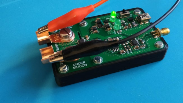
A decent current measurement sensor ought to be an essential part of every hacker’s workbench. One that is capable of measuring DC, as well as low and high frequencies with reasonable accuracy. And bonus credits if it can also withstand high bus voltages – such as those found in mains utility or electric vehicle work. [Undersilicon] couldn’t find one that ticked all the boxes, so he built an ACS730 based AC/DC current probe capable of measuring up to 25 A at frequencies up to 1 MHz.
Allegro Microsystems has a wide offering of current sensor IC’s. The ACS730 features a -3 dB bandwidth of 1 MHz, and -1 dB bandwidth of 500 kHz. Since it is galvanically isolated, it can be used in AC mains applications up to 297 Vrms and for DC up to 420 V. And as he intended to use it as an oscilloscope accessory, the analog output suited the application nicely. A pair of precision op-amps provide the voltage output scaled to 100 mV/A. The board is powered off a 1000 mAh LiPo battery that can run the sensor for about 15 ~ 20 hours. The power supply section consists of a charge circuit for the LiPo, and a split rail dual output power supply converter for the op-amps.
The ACS730 has a 2.5 V output when measured current is zero, and is scaled for 40 mV/A. This gives an output voltage swing from -0.5 V for -50 A to +4.5 V for +50 A. This is where the AD823ARZ dual 16 MHz, Rail-to-Rail FET Input Amplifiers step in. One pair is used to obtain a 2.5 V reference from the 5 V supply, and also to buffer the analog output from the ACS730. The second pair subtracts the 2.5 V offset, and applies a gain of 2.5 to get the 100 mV/A output. Dual power supply for the op-amps comes from a TPS65133 Split-Rail Converter, ±5V, 250mA Dual Output Power Supply. Lastly, LiPo charging is handled by the MCP73831 Single Cell, Li-Ion/Li-Polymer Charge Management Controller.
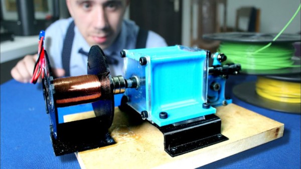
Before Tesla devised beautifully simple rotary machinery, he explored other methods of generating alternating current. One of those was the mechanical oscillator, and [Integza] had a go at replicating the device himself. (Video, embedded below the break.)
Initial attempts to reproduce the technology using 3D-printed parts were a failure. The round cylinder had issues sealing, and using O-ring seals introduced too much friction to allow the device to oscillate properly. A redesign that used external valving and a square cylinder proved more successful.
Once the oscillator was complete, the output shaft was fitted with magnets and a coil to generate electricity. After generating a disappointing 0.14 volts, [Integza] went back and had a look at the Maxwell-Faraday equations. Using this to guide the design, a new coil was produced with more turns, and the magnetic flux was maximised. With this done, the setup could generate seven volts, enough to light several LEDs.
While it’s not a particularly efficient generator, it’s a great proof-of-concept. Yes, Tesla’s invention worked, but it’s easy to see why he moved on to rotary designs when it came to real-world applications. We’ve seen [Integza] take on other builds too, like the ever-popular Tesla turbine.
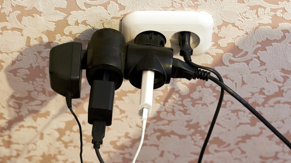
During my recent trip to Europe, I found out that converters were not as commonly sold as adapters, and for a good reason. The majority of the world receives 220-240 V single phase voltage at 50-60 Hz with the surprisingly small number of exceptions being Canada, Colombia, Japan, Taiwan, the United States, Venezuela, and several other nations in the Caribbean and Central America.
While the majority of countries have one defined plug type, several countries in Latin America, Africa, and Asia use a collection of incompatible plugs for different wall outlets, which requires a number of adapters depending on the region traveled.
Although there is a fair degree of standardization among most countries with regards to the voltage used for domestic appliances, what has caused the rift between the 220-240 V standard and the 100-127 V standards used in the remaining nations?
How many of you plan to build a wind-powered generator in the next year? Okay, both of you can put your hands down. Even if you don’t want to wind your coils manually, learning about the principles in an electric generator might spark your interest. There is a lot of math to engineering a commercial model, but if we approach a simple version by looking at the components one at a time, it’s much easier to understand.
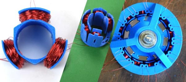
For this adventure, [K&J Magnetics] start by dissect a commercial generator. They picked a simple version that might serve a campsite well, so there is no transmission or blade angle apparatus to complicate things. It’s the parts you’d expect, a rotor and a stator, one with permanent magnets and the other with coils of wire.
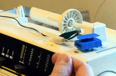
The fun of this project is copying the components found in the commercial hardware and varying the windings and coil count to see how it affects performance. If you have ever wound magnet wire around a nail to make an electromagnet, you know it is tedious work so check out their 3D printed coil holder with an embedded magnet to trigger a winding count and a socket to fit on a sewing machine bobbin winder. If you are going to make a bunch of coils, this is going to save headaches and wrist tendons.
They use an iterative process to demonstrate the effect of multiple coils on a generator. The first test run uses just three coils but doesn’t generate much power at all, even when spun by an electric drill. Six windings do better, but a dozen finally does the trick, even when turning the generator by hand. We don’t know about their use of cheap silicone diodes though, that seems like unintentional hobbling, but we digress.
Making turbine blades doesn’t have to be a sore chore either, and PVC may be the ticket there, you may also consider the vertical axis wind turbine which is safer at patio level. Now, you folks building generators, remember to tip us off!
Sure, you could animate some Halloween lights using a microcontroller, some random number generation and some LEDs, and if the decorations are powered by AC, you could use some relays with your microcontroller. What if you don’t have that kind of time? [Gadget Addict] had some AC powered decorations that he’d previously animated with an Arduino and some relays, but this year wanted to do something quicker and simpler.
In another video, he goes over the wiring of a fluorescent starter to create a flickering effect with an incandescent light bulb. A fluorescent starter works because the current heats up a gas discharge tube which causes a bit of metal to bend and touch another, closing the circuit. A fluorescent bulb is a big enough load that the flowing current keeps the starter hot and, therefore, the circuit closed. If you wire the starter in series with a regular incandescent bulb, the starter heats up but the load isn’t big enough to keep the starter hot enough, so it cools down and the circuit breaks, which causes the starter to heat up again. This causes the bulb to flicker on and off. [Gadget Addict] uses two circuits with a fluorescent starter each wired to alternate bulbs in the decoration in order to get the effect to look a bit more random.
The laptop I’m using, found for 50 bucks in the junk bins of Akihabara has a CPU that runs at 2.53GHz. Two billion five hundred and thirty million times every second electrons systematically briefly pulse. To the human mind this is unimaginable, yet two hundred years ago humanity had no knowledge of electrical oscillations at all.
There were clear natural sources of oscillation of course, the sun perhaps the clearest of all. The Pythagoreans first proposed that the earth’s rotation caused the suns daily cycle. Their system was more esoteric and complex than the truth as we now know it and included a postulated Counter-Earth, lying unseen behind a central fire. Regardless of the errors their theory contained, a central link was made between rotation and oscillation.
And rotational motion was exploited in early electrical oscillators. Both alternators, similar to those in use today, and more esoteric devices like the interrupter. Developed by Charles Page in 1838, the interrupter used rocking or rotational motion to dip a wire into a mercury bath periodically breaking a circuit to produce a simple oscillation.
As we progressed toward industrial electrical generators, alternating current became common. But higher and higher frequencies were also required for radio transmitters. The first transmitters had used spark gaps. These simple transmitters used a DC supply to charge a capacitor until it reached the breakdown voltage of the gap between two pieces of wire. The electricity then ionized the air molecules in the gap. Thus allowing current to flow, quickly discharging the capacitor. The capacitor charged again, allowing the process to repeat.
As you can see and hear in the video above spark gaps produce a noisy, far from sinusoidal output. So for more efficient oscillations, engineers again resorted to rotation.
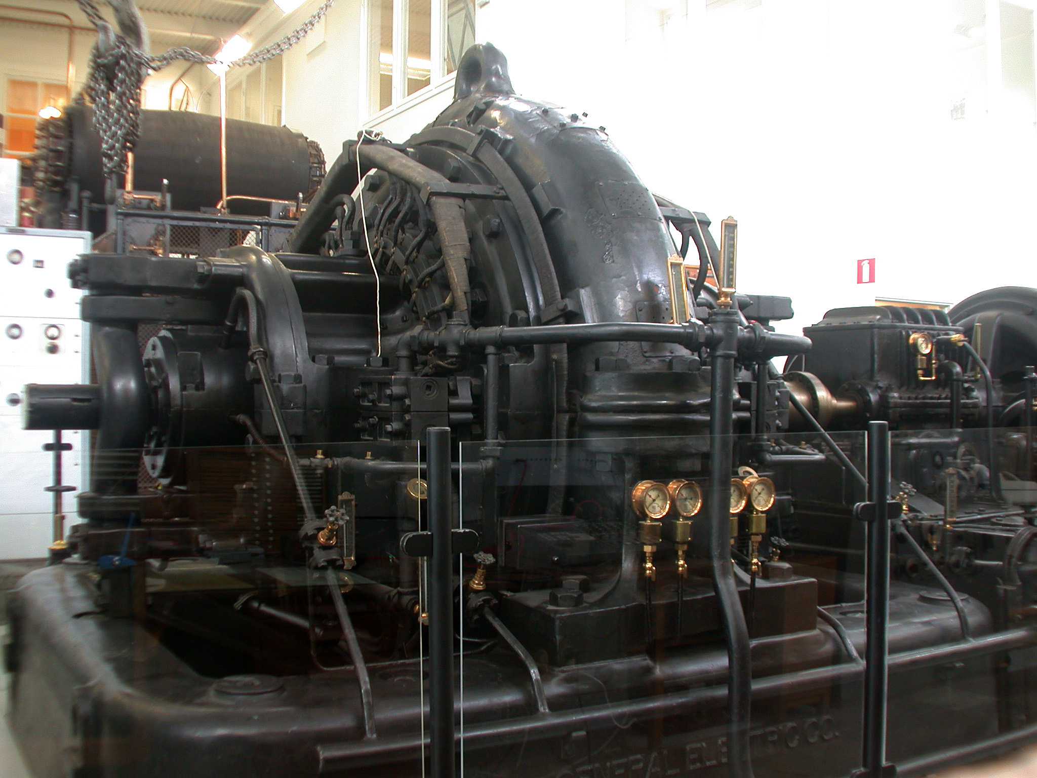
The Alexanderson alternator uses a wheel on which hundreds of slots are cut. This wheel is placed between two coils. One coil, powered by a direct current, produces a magnetic field inducing a current in the second. The slotted disc, periodically cutting this field, produces an alternating current. Alexanderson alternators were used to generate frequencies of 15 to 30 KHz, mostly for naval applications. Amazingly one Alexanderson alternator remained in service until 1996, and is still kept in working condition.
A similar principal was used in the Hammond organ. You may not know the name, but you’ll recognize the sound of this early electronic instrument:
The Hammond organ used a series of tone wheels and pickups. The pickups consist of a coil and magnet. In order to produce a tone the pickup is pushed toward a rotating wheel which has bumps on its surface. These are similar to the slots of the Alexanderson Alternator, and effectively modulate the field between the magnet and the coil to produce a tone.
Amplifying the Oscillation
The operation of a tank circuit (from wikipedia)
So far we have purely relied on electromechanical techniques, however amplification is key to all modern oscillators, for which of course you require active devices. The simplest of these uses an inductor and capacitor to form a tank circuit. In a tank circuit energy sloshes back and forth between an inductor and capacitor. Without amplification, losses will cause the oscillation to quickly die out. However by introducing amplification (such as in the Colpitts oscillator) the process can be kept going indefinitely.
Oscillator stability is important in many applications such as radio transmission. Better oscillators allow transmissions to be packed more closely on the spectrum without fear that they might drift and overlap. So the quest for better, more stable oscillators continued. Thus the crystal oscillator was discovered, and productionized. This was a monumental effort.
Producing Crystal Oscillators
The video below shows a typical process used in the 1940s for the production of crystal oscillators:
Natural quartz crystals mined in Brazil were shipped to the US, and processed. I counted a total of 13 non-trivial machining/etching steps and 16 measurement steps (including rigorous quality control). Many of these quite advanced, such as the alignment of the crystal under an X-Ray using a technique similar to X-Ray crystalography.
These days our crystal oscillator production process is more advanced. Since the 1970s crystal oscillators have been fabricated in a photolithographic process. In order to further stabilize the crystal additional techniques such as temperature compensation (TCXO) or operating the crystal at a temperature controlled by the use of a heating element (OCXO) have been employed. For most applications this has proved accurate enough… Not accurate enough however for the timenuts.
Timenuts Use Atoms
Typical timenut wearing atomic wristwatch
For timenuts there is no “accurate enough”. These hackers strive to create the most accurate timing systems they can, which all of course rely on the most accurate oscillator they can devise.
Many timenuts rely on atomic clocks to make their measurements. Atomic clocks are an order of magnitude more precise than even the best temperature controlled crystal oscillators.
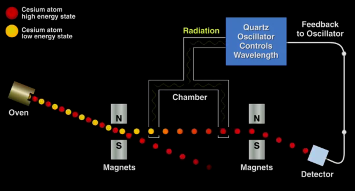
Bill Hammack has a great video describing the operation of a cesium beam oscillator. The fundamental process is shown in the image below. The crux is that cesium gas exists in two energy states, which can be separated under a magnetic field. The low energy atoms are exposed to a radiation source, the wavelength of which is determined by a crystal oscillator. Only a wavelength of exactly 9,192,631,770Hz will convert the low energy cesium atoms to the high energy form. The high energy atoms are directed toward a detector, the output of which is used to discipline the crystal oscillator, such that if the frequency of the oscillator drifts and the cesium atoms are no longer directed toward the detector its output is nudged toward the correct value. Thus a basic physical constant is used to calibrate the atomic clock.
The basic operating principle of a cesium atomic clock
While cesium standards are the most accurate oscillators known, Rubidium oscillators (another “atomic” clock) also provide an accurate and relatively cheap option for many timenuts. The price of these oscillators has been driven down due to volume production for the telecoms industry (they are key to GSM and other mobile radio systems) and they are now readily available on eBay.
With accurate time pieces in hand timenuts have performed a number of interesting experiments. To my mind the most interesting of these is measuring time differences due to relativistic effects. As is the case with one timenut who took his family and a car full of atomic clocks up Mt. Rainier for the weekend. When he returned he was able to measure a 20 nanosecond difference between the clocks he took on the trip and those he left at home. This time dilation effect was almost exactly as predicted by the theory of relativity. An impressive result and an amazing family outing!
It’s amazing to think that when Einstein proposed the theory of special relatively in 1905, even primitive crystal oscillators would not have been available. Spark gap, and Alexanderson alternators would still have been in everyday use. I doubt he could imagine that one day the fruits of his theory would be confirmed by one man, on a road trip with his kids as a weekend hobby project. Hackers of the world, rejoice.
I finally did it. After years of wanting one (and pushing off projects because I didn’t have one) I finally bought an oscilloscope. Over the years I read and watched a ton of content about how to use a scope, you’d think I would know what I’m doing. Turns out that, like anything, hands-on time with an oscilloscope quickly highlighted the gaping holes in my knowledge. And so we begin this recurring column called Scope Noob. Each installment will focus on a different oscilloscope-related topic. This week it’s measuring a test signal and probing Alternating Current.
Measuring a Signal
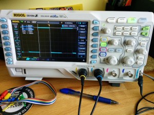
Hey, measuring signals is what oscilloscopes are all about, right? My very first measurement was, of course, the calibration signal built into the scope. As [Chris Meyer] at Sector67 hackerspace here in Madison put it, you want to make sure you can probe a known signal before venturing into the unknown.
In this case I’m using channel 2. Everything on this scope is color-coded, so the CH2 probe has blue rings on it, the probe jack has a blue channel label, and the trace drawn on the screen is seen in blue. I’m off to a fantastic start!
This scope, a Rigol 1054z, comes with an “auto” button which will detect the signal and adjust the divisions so that the waveform is centered on the display. To me this feels like a shortcut so I made sure to do all of this manually. I started with the “trigger” which is a voltage threshold at which the signal will be displayed on the screen. The menu button brings up options that will let you choose which channel to use as trigger. From there it was just a matter of adjusting the horizontal and vertical resolution and position before using the “cursor” function to measure the wave’s voltage and time.
I played around with the scope a bit more, measuring some PWM signals from a microcontroller. But you want to branch out. Because I don’t have a proper signal generator, the next logical thing to measure is alternating current in my home’s electrical system. I suppose you could call it a built-in sine wave source.
Probing Alternating Current
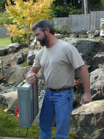
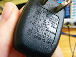
I sometimes take criticism for never throwing things away. Seven years ago we had a cat water fountain whose motor seized. It was powered by a 12V AC to AC converter seen here. Yep, I kept it and was somehow able to find it again for this project.
Of course at the time I thought I would build a clock that measures mains frequency to keep accurate time. This would have done the trick had I followed through. But for now I’m using it to protect me (and my fancy new scope) from accidental shock. I’ll still get the sine wave I’m looking for but with a source that is only 12V at 200 milliamps.
Don’t measure mains directly unless you have a good reason to do so.
Continuing on my adventure I plugged in the wall wart and connected the probe to one of the two wires coming out of it. But wait, what do I do with the probe’s reference clip? I know enough about home electrical to know that one prong of the plug is hot, the other is neutral. The clip itself is basically connected directly to mains ground. Bringing the two together sounds like a really bad idea.
This turns out to be a special case for oscilloscopes, and one that prompted me to think about writing this column. Had this been a 3-prong wall wart, connecting the probe’s reference clip to one of the wires would have been a very bad thing. Many 3-prong wall warts reference the mains earth ground on one of the outputs. If that were the case you could simply leave the clip unconnected as the chassis ground of your scope is already connected to mains ground via its own 3-prong power cord and the reference clip is a dead short to that. If you did need to probe AC using the reference clip you need an isolation transformer for your scope. There are bigger implications when probing a board powered from mains which [Dave Jones] does an excellent job of explaining. Make sure you check out his aptly named video: How NOT to blow up your oscilloscope.
As I understand it, and I hope you’ll weigh in with a comment below, since the wall wart I’m using has a transformer and no ground plug I’m fine using the ground clip of the probe in this case. Even though I’m clipping it to an AC line, the transformer prevents any kind of short between hot/neutral mains and earth ground (via the probe’s ground clip). What I don’t understand is why it’s okay to connect the transformed side of the 12V AC to mains ground?
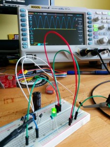
At any rate, the screenshots above show my progress through this measurement. I first connected the probe without the ground clip and got the sad-looking trace seen on the left. After conferring with both [Adam Fabio] and [Bil Herd] (who had differing opinions on whether or not I should “float the scope”) I connected the ground clip and was greeted with a beautifully formed sine wave. I’m calling this a success and putting a notch in the old bench to remember it by.
What’s Next?
I don’t want to get too crazy with the first installment of Scope Noob so I’ll be ending here for now. I need your guidance for future installments. What interesting quirks of an oscilloscope should a noob like me explore? What are your own questions about scope use? Leave those below and we’ll try to add them to the lineup in the coming weeks.
Homework
For next week I’m working my way through the adventure of rectifying this 12V AC signal into a smoothed DC source. Here you see a teaser of those experiments. I’ve built a full-wave rectifier using just four diodes (1N4001) and will plunk in a hugely-over-spec’d electrolytic capacitor to do the smoothing. If you want to follow along on the adventure you should dig around your parts drawers for these components and give it a try yourself this week. We’ll compare notes in the next post!


 The fun of this project is copying the components found in the commercial hardware and varying the windings and coil count to see how it affects performance. If you have ever wound magnet wire around a nail to make an electromagnet, you know it is tedious work so check out their 3D printed coil holder with an embedded magnet to trigger a winding count and a socket to fit on a sewing machine bobbin winder. If you are going to make a bunch of coils, this is going to save headaches and wrist tendons.


 I don’t want to get too crazy with the first installment of Scope Noob so I’ll be ending here for now. I need your guidance for future installments. What interesting quirks of an oscilloscope should a noob like me explore? What are your own questions about scope use? Leave those below and we’ll try to add them to the lineup in the coming weeks.


