Some Of The Many Ways To Build AM Transmitters And Receivers

AM radios are relatively simple devices, and building one is a good way to start exploring the world of radio communications. [GreatScott] does exactly this in the video after the break, building both a transmitter and receiver.

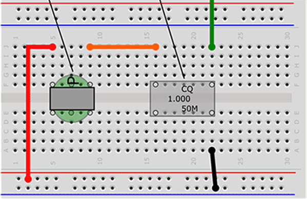
At the most basic level, AM radio works by generating a carrier wave with an oscillator, and then modulating the amplitude with an audio signal. Around these parts, the venerable 555 timer is always brought up whenever things get to oscillating; so you’ll no doubt be happy to see [GreatScott] decided to give it a shot for his first experiments, testing two popular 555 transmitter circuits. One uses the control voltage pin to input the audio signal, while the other uses the reset pin. The CV-pin version worked slightly better, but it was still just barely possible to distinguish a voice over a standard commercial AM/FM receiver.

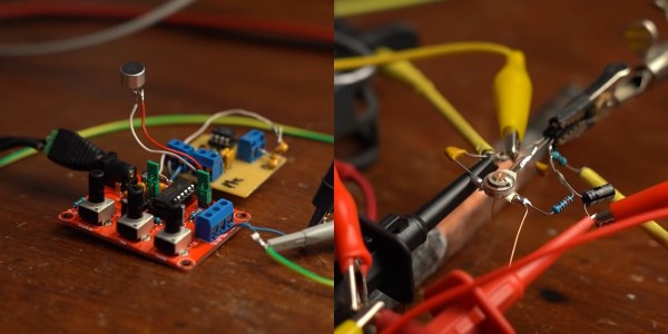
The next attempt was with a XR2206 function generator kit, which worked quite well when combined with a simple microphone amplifier circuit. But this time the receiving side was swapped out, as [GreatScott] built a basic circuit around a TA7642 AM amplifier/demodulator IC, with only six passive components and a hand-wound coil.

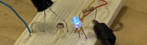
There is no shortage of ways to build AM radios, and we’ve covered quite a few over the years. Off course a 555 timer can also be used in a receiver, and building transmitters using only discrete components is quite simple, as demonstrated by the 10-minute transmitter and single transistor transmitter.

Continue reading “Some Of The Many Ways To Build AM Transmitters And Receivers”

A Simple Science Fair AM Transmitter

A crystal radio is a common enough science fair project, but the problem is, there isn’t much on anymore. The answer is, of course, obvious: build your own AM transmitter, too. AM modulation isn’t that hard to do and [Science Buddies] has plans for how to build one with a canned oscillator and an audio transformer.

We don’t imagine the quality of this would be so good, but for a kid’s science project it might be worth a shot. Maybe something like “What kind of materials block radio waves?” would be a good project statement.

Continue reading “A Simple Science Fair AM Transmitter”

A Tube AM Transmitter In A Soup Can

A standard early electronics project or kit has for many years been the construction of a small broadcast transmitter with enough power to reach the immediate area, but no further. These days that will almost certainly mean an FM broadcast band transmitter, but in earlier decades it might also have been for the AM broadcast band instead.

The construction of a small AM transmitter presents some interesting problems for an electronic designer. It is extremely easy to make an AM transmitter with a single transistor or tube, but it is rather more difficult to make a good one. The modulation has to be linear across the whole amplitude range, and its effect must not pull the frequency of the oscillator and cause FM distortion.

It’s a task [Joe Sousa] has tackled, with his one tube AM transmitter in a Campbell’s soup can. His write-up of the transmitter contains a full description of the problems he faced, and how his design overcomes them. His oscillator is a cathode follower, with the tube biased in class A mode to ensure as undistorted a sine wave oscillation as possible. Modulation is provided through the suppressor grid of the pentode tube he’s using.

The completed transmitter is mounted inside the iconic soup can, with the mains transformer mounted on a removable bottom plate. There is a provision for both loop and wire antennas to be connected.

It is probable that this transmitter falls under the so-called “Part 15” rules for unlicenced low-power broadcasting in the USA, however it should be borne in mind that not every territory has this provision. If you build this transmitter, make sure you’re not going to attract the interest of your local equivalent of the FCC.

This article should have whetted your appetite for tiny broadcast transmitters. How about comparing the one here with a full-sized model?

Thanks [2ftg] for the tip.

A Vintage Single Transistor LED Blinker

[Eric Wasatonic] had a box of SWB2433 transistors that he had very little information about. In order to discover their properties, he fired up his curve tracer to compare these transistors with more common ones. He noticed the SWB2433 exhibited negative resistance while the similar curves of a 2n3904 didn’t. Then he reverse-biased the two transistors: the negative resistance region on the 2n3904 was less than that of the SWB2433, but it was there, and a 2n2222 had a bigger region. Using this knowledge, he developed a relaxation oscillator circuit which uses a negatively biased transistor.

Using one transistor, one resistor and one capacitor, he describes the circuit and how the components affect the frequency of the sawtooth wave the oscillator creates. [Eric] uses the oscillator to build a simple LED blinker and shows what happens when he changes the transistor and adjusts the voltage or resistance. He also shows the circuit as a tone generator and adjusts the tone by replacing the resistor with a potentiometer. And then, for fun, he modifies the circuit to show the oscillator as an AM transmitter. Check out his video after the break.

Continue reading “A Vintage Single Transistor LED Blinker”