Reel In The Years With A Cassette Player Synth

Variable-speed playback cassette players were already the cool kids on the block. How else are you going to have any fun with magnetic tape without ripping out the tape head and running it manually over those silky brown strips? Sure, you can change the playback speed on most players as long as you can get to the trim pot. But true variable-speed players make better synths, because it’s so much easier to change the speed. You can make music from anything you can record on tape, including monotony.

[schollz] made a tape synth with not much more than a variable-speed playback cassette player, an Arduino, a DAC, and a couple of wires to hook it all up. Here’s how it works: [schollz] records a long, single note on a tape, then uses that recording to play different notes by altering the playback speed with voltages from a MIDI synth.

To go from synth to synth, [schollz] stood up a server that translates MIDI voltages to serial and sends them to the Arduino. Then the DAC converts them to analog signals for the tape player. All the code is available on the project site, and [schollz] will even show you where to add Vin and and a line in to the tape player. Check out the demo after the break.

There’s more than one way to hack a cassette player. You can also force them to play full-motion, color video.

Continue reading “Reel In The Years With A Cassette Player Synth”

Hypnotic Visuals Synthesizer

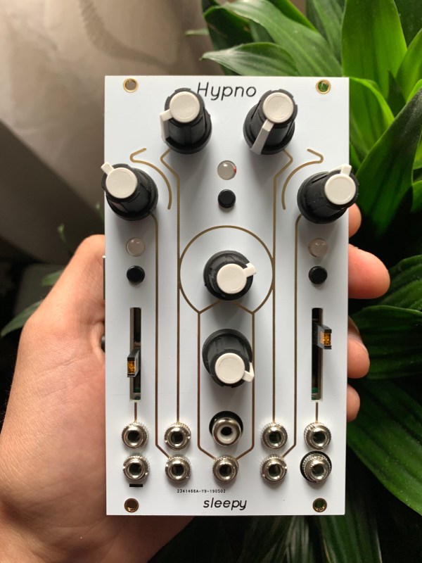
Ever wanted to make some seriously trippy retro graphics to go along with your lo-fi hip hop beats? Now you can, with [teafella]’s aptly named Hypno Video Synthesizer, a Raspberry Pi-based video synthesizer that digitally emulates and extends analog video workflows through colorization, shape generation, and feedback, patching the modifications into a compact interface. The device allows music creators to perform with live visuals, or alternatively to create a unique visual source for a video setup. Once the CV input is plugged in, all it requires is a composite display and power to start working.

Hypno takes input through a control voltage (CV) jack using a MCP3008 ADC via SPI, with voltages scaled from -5-5V to 0-5V. The device attaches on top of a Raspberry Pi, using Raspbian for the operating system and the Pi Zero GPIO to interface with an OpenGL Engine. The input parameters are taken from knobs through a multiplexer into a single channel of the ADC, with values offset in software based on the CV inputs.

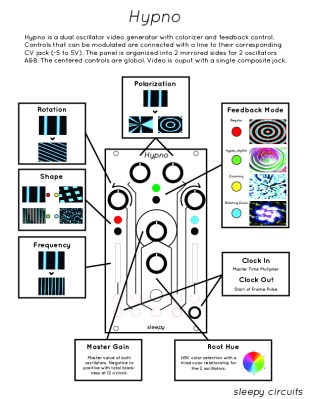
Using the Hypno ends up being fairly straight forward, as the controls are organized onto two mirrored sides for the two oscillators A & B, with global controls in the center. There are knobs that control polarization, rotation, shape, feedback modes (regular, hyper digital, zooming, rotating zoom), clock in/clock out, frequency, root hue, and master gain, as well as RGB LEDs that provide visual feedback.

A single jack outputs the composite result, although a micro-HDMI plug can also be used on the back. For advanced functionality, Hypno allows for patching, which mixes effects on top of one another and allows for shapes such as oscillator cross modulation. There are also alt-controls that open up self modulation and other shapes. Examples include bipolar drift (smoothly scrolls the oscillator) and mirroring (mirrors the oscillator’s shape in different patterns for a kaleidoscope-eque tiled madness).

The software is written in C++ and GLSL, with the main engine running with one plane in OpenGL, drawing the output of a GLSL shader. The CV and knob inputs are fed into shader uniforms that are used to change the visuals in the engine.

[teafella], a self-professed Arduino user, uses WiringPi for the GPIO interactions. The Shader system is inspired by analog video synthesis, with every shape having a simulated “scan” over the screen and function mapped to it that can be transformed into polar coordinates.

The setup for Hypno is fully compatible with analog CV equipment such as Eurorack synthesizers, which makes it easy for music creators to plug and play. Here’s a couple of sample outputs from some soundtracks inputted into Hypno:

Too many combinations to even imagine? Check out a demo of Hypno in action!

Continue reading “Hypnotic Visuals Synthesizer”

Mechanizing A Eurorack Sequencer

Eurorack has taken over the synthesizer community, and hundreds of people are building their own eurorack modules. [Michael Forrest] designed and built his own Eurorack sequencer module that doesn’t use weird things like capacitors and chips to store a signal. Instead, he’s doing it with stepper motors and some clever engineering.

The basic idea of a Eurorack sequencer is to somehow store a series of values and play them back repeatedly. Connect that sequence to a clock, and you get the same pattern of sounds out of your synth. This can be done digitally with a circular buffer, in the analog domain with a bunch of FETs and caps, or in this case, on a piece of paper glued to a stepper motor.

The key bit of mechanism for this build is a stepper motor with 96 steps per rotation. This is important, because the module is controlled by a clock pulse from the sequencer. Since 96 is evenly divisible by 8 and 16, that means this sequencer will play back in 4/4 time. That NEMA 17 motor with 200 steps per resolution simply won’t work in this situation. Rather, it will technically work, but it’ll be unusable.

The electronics for this build are surprisingly simple, with an Arduino taking in the clock pulse and sending the step signals to an H-driver. The motor spins a paper disk, which is read with a photoresistor and a LED. It’s simple enough to be fun, and yes, it is mounted to a proper Eurorack-sized panel. You can check out the video of this build below.

Continue reading “Mechanizing A Eurorack Sequencer”

Restoring A Piece Of Musical History

Every restoration project involves various levels of grit, determination, gumption and doggedness. But [Darren Glen]’s restoration of a Jupiter-8 is an absolute labor of love. The Jupiter-8,  launched by Roland in 1981, was their flagship “polyphonic analog subtractive” synthesizer and was used by many legendary acts of the ’80’s. The synthesizer was rugged — built to withstand the rigors of travelling everywhere that the bands took it. More importantly, it could produce a wide range of sounds that came from dedicated and independent controllers. These, plus a host of other desirable features, makes the synth highly coveted even today and the rare ones that surface for sale can be quite expensive.

The back story of how he came in possession of this coveted, albeit non-functioning, piece of history is a good read. But the part that makes us all interested is the meticulous restoration that he is carrying out. There is a lot of useful information that he shares which could be handy if you are planning any restoration project of your own.

When he first turned it on, all he got was an “8” on the display — which seemed like an error code. From then onward, he has been carefully stripping away each part and slowly bringing it back to life. All of the linear slide potentiometers and slide switches were de-soldered, dis-assembled, cleaned of rust and the carbon tracks and contacts cleaned with special spray — making them almost as good as new. The transformer and its mounting brackets received a similar treatment of rust cleaning and fresh paint. All of the other internal metal parts, such as the chassis, were restored in a similar fashion.

White plastic buttons and knobs which were faded, were brightened up by spraying them with a generous dose of hydrogen peroxide hair spray, putting them in Ziploc bags and letting them bake in sunlight for a day. [Darren] was satisfied enough with this process and gave the same treatment to all the other colored buttons too, with good results. The other set of plastic parts – the keyboard keys, were cleaned and polished with a scratch and blemish polish cream, and replacements were ordered out from a specialist supplier for the few that were damaged beyond repair.

But by far the greatest challenge for [Darren] has been resurrecting the top metal cover. It was badly rusted and had to be completely stripped of all paint. Repainting it the right shade was relatively easy, but applying the legend and decals took him to every screen printer in town, none of whom could manage the job. He lucked out by locating a screen printer who specialized in custom automotive work and managed to do a pretty good job with the decal work.

The Z80 microprocessor had lost all its magic smoke, so [Darren] has ordered an original Zilog replacement which will hopefully clear the error he noticed when it was first turned on. He’s slowly working his way through all the issues, and it is still work in progress, but we look forward to when it’s all done and dusted. A fully functional, restored Roland Jupiter-8 — one of the first 500 that were built back in 1981 — resurrected with a lot of TLC.

A big shout out to [Tim Trzepacz] for bringing this project to our notice.

Controlling A Moog Werkstatt With A Capacitive Touch Jankó Keyboard

[Ben Bradley], a member of Freeside Atlanta, built a capacitive touch Jankó keyboard for the Georgia Tech Moog Hackathon. Jankó Keyboards are a 19th-Century attempt to add a more compact piano keyboard. There are three times as many keys as a traditional piano but arranged vertically for (supposedly) greater convenience while playing–an entire octave can be covered with one hand. But yeah, it never caught on.

[Ben]’s project consists of a series of brass plates wired to capacitive touch breakout boards from Adafruit, one for each of the Arduino Mega clone’s four I2C addresses. When a key is touched, the Arduino sends a key down signal to the Werkstatt while using a R-2R ladder to generate voltage for the VCO exponential input.

The most recent Moog Hackathon was the third.  Twenty-five teams competed from Georgia Tech alone, plus more from other schools, working for 48 hours to build interfaces with Moog Werkstatt-Ø1 analog synths, competing for $5,000 in cash prizes as well as Werkstatts for the top three teams.

We’re synth-fiends here on Hackaday: we cover everything from analog synths to voltage controlled filters.

Via Freeside Atlanta, photo by [Nathan Burnham].

Continue reading “Controlling A Moog Werkstatt With A Capacitive Touch Jankó Keyboard”

NES Light Gun Turned (Video) Synthesizer

[Russell Kramer] made our day today. We’re tremendous fans of minimalism in electronics design, dirty noise hacks, and that old NES  light gun. He’s posted up a project that combines all three to make a light-gun controlled, VGA video display that makes bleepy-bloopy noises to boot. Check out the video below!

To appreciate this hack, you really need to read through the project logs in detail. Start with the VGA signal creation, for instance. The easiest way to go these days is to throw a microcontroller at the problem. But because he’s done that to death, [Russell] takes a step back thirty years and generates the sync pulses periodically with a relaxation oscillator and a binary counter IC. The rest of the build follows this aesthetic choice: everything is op amps and CMOS logic. The rainbow effect, for instance, is created from the audio signal through a three-stage, 120-degree phase-shift oscillator sent to the R, G, and B channels. Kudos!

The high-level overview is that the light intensity and position hitting the gun’s sensor is converted into a voltage that drives an audio-frequency oscillator. This audio output is then piped back into the video generator. Watching the video, it’s obvious that pointing the gun at different parts of the screen changes the pitch, but playing a given pitch is nearly impossible on this thing with all the feedback going on. [Russell] added a bit of more control into the system — when the gun’s trigger is pulled, it registers full-brightness regardless of the video input — but even so, we’d be hard-pressed to play “Mary Had a Little Lamb”.

But that’s not the point. The point is awesome, light-gun-waving noisy madness set to a responsive colorful video background. And that’s been achieved in spades!

Continue reading “NES Light Gun Turned (Video) Synthesizer”

Oh Baby, Baby10 – Build A Classic Analog Music Sequencer

Recently I’ve been learning more about classic analog music synthesizers and sequencers. This has led me to the Baby10, a classic and simple analog sequencer design. In this article I’ll introduce its basic operation, and the builds of some awesome hackers based on this design.

Sequencers produce, a sequence of varying voltages. These control voltages (CV) can then be use to control other components. Often this is a simple tone generator. While the concept is simple, it can produce awesome results:

A basic sequencer is a great beginners project. It’s easy to understand the basic operation of the circuit and produces a satisfyingly entertaining result. The Baby 10 was originally published in a column called “Captain’s Analog”, but has now been widely shared online.

baby10
The original Baby10 article.

The circuit uses the 4017, a simple CMOS decade counter. The 4017 takes an input clock signal then sequentially outputs a high pulse on each of 10 output pins. As such, the 4017 does almost everything we need from a sequencer in a single IC! However, we want our sequencer to output a varying voltage which we can then use to generate differing tones.

To accomplish this variable resistors are connected to each of the output pins. A diode in series with the variable resistor stops the outputs fighting against each other (in layman’s terms).

To make the sequencer more visually attractive (and give some feedback) LEDs are often also added to the output of the 4017. A complete Baby 10 sequencer is shown in the schematic below. The original circuit used 1N917s, these are no longer available but the part has been replaced by the 1N4148.

Continue reading “Oh Baby, Baby10 – Build A Classic Analog Music Sequencer”