The Other Kind Of Static Hazard To Your Logic Circuits

We’ve all heard of the dangers of static electricity when dealing with electronics, and we all take the proper precautions when working with static-sensitive components — don’t we? But as much as we fear punching an expensive hole in a chip with an errant spark, electrostatic discharge damage isn’t the only kind of static hazard your digital designs can face.

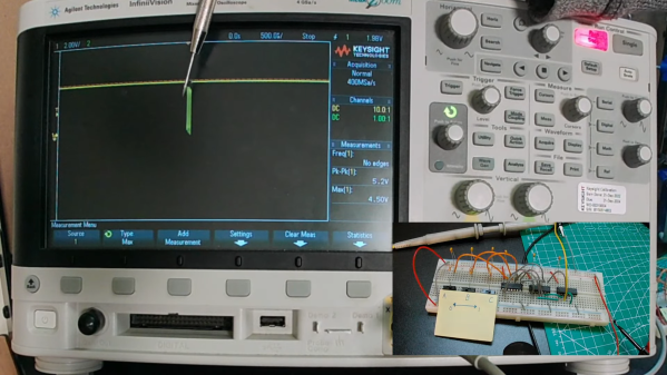
To be fair, the static hazard demonstrated by [Shane Oberloier] in the video below isn’t really an electrostatic problem. “Static” in this case refers to when a change to an input of a logic circuit gives an unexpected output until the circuit stabilizes. The circuit shown is pretty simple, with three inputs going into a combination of AND and NOT gates before going into an OR gate. The static hazard manifests as a glitch in the output when the middle input line’s logical state is toggled; according to the circuit’s truth table, the output shouldn’t change under these conditions, but the oscilloscope clearly captures a high-low-high blip. [Dr. Shane]’s explanation of why this happens makes perfect sense: the inverter on that input line has a brief but non-zero propagation time, putting the whole circuit in an ambiguous state before finally settling down to the correct output value.

So how do you fix something like this? This gets into the Boolean weeds a bit, and we won’t pretend to fully understand it, but at least for this case, [Dr. Shane] was able to add a single AND gate to sum the two other inputs and pipe the output into another input of the OR gate. That has the effect of canceling out the race condition caused by the inverter, but at the expense of a more complicated circuit, of course.

We found this to be a fascinating and informative discussion of a potential pitfall in logic design. But, if you still want to see some MOSFETs executed with static electricity, who are we to object?

Continue reading “The Other Kind Of Static Hazard To Your Logic Circuits”

Partial Relay-Based Calculator Puts The Click Where It Counts

It looks like [Michal Zalewski] is raising the next generation the right way. First, his eldest son asks for help building a one-bit computer from discrete transistors. Not to be left behind, his little brother then asked for help with an even more retro project, which resulted in this partially relay-based calculator. Maybe there is some hope for the future.

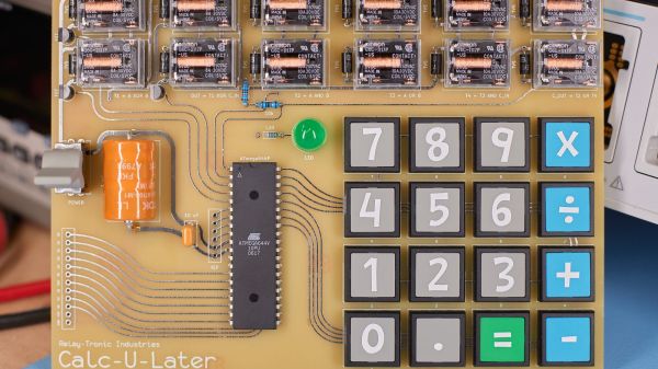
Now, purists will no doubt notice the ATmega64 microcontroller sitting in the middle of the main PCB on this project and cry “Foul!” But perfect is the enemy of done, and as [Michal] explains, at $6 a pop for the Omron relays he and his son chose, there’s only so far you can go with relay logic before you’re taking out a second mortgage. So the relays are limited to the ALU of the calculator, along with the drivers for the six seven-segment LED displays. The microcontroller is just there for housekeeping functions like scanning the keyboard and decoding digits. All the actual calculations are in the relay logic, not silicon. And we’d be remiss not to praise his son’s stylistic choices for this design — that it uses relays with clear covers, and that it has single-sided PCBs with curvy, hand-drawn traces traces that look hand-drawn on old-school yellow substrate. [Michal]’s heart must swell with pride to have fathered someone with such exquisite taste.

For his part, [Mikal] did some really good documentation for this build, including excellent descriptions of Boolean math with half- and full-adders and how relays are used to create the basic logic gates that comprise them. The calculator itself is still a work in progress, with microcontroller code still in development, but it’s working enough that you can enjoy the display driver’s clickiness in the video below. If that doesn’t do it for you, we’ve got other relay calculators to scratch that click itch. Continue reading “Partial Relay-Based Calculator Puts The Click Where It Counts”

Interference Patterns Harnessed For Optical Logic Gates

The basics of digital logic are pretty easy to master, and figuring out how the ones and zeroes flow through various kinds of gates is often an interesting exercise. Taking things down a level and breaking the component AND, OR, and NOR gates down to their underlying analog circuits adds some complexity, but the flow of electrons is still pretty understandable. Substitute all that for photons, though, and you’ll enter a strange world indeed.

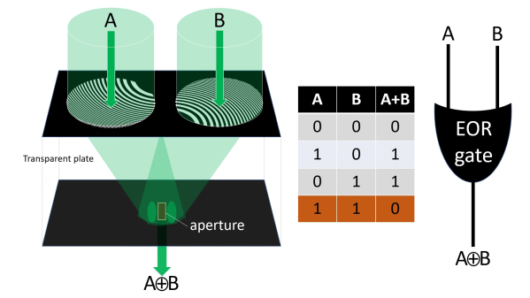
At least that’s our take on [Jeroen Vleggaar]’s latest project, which is making logic gates from purely optical components. As he himself admits in the video below, this isn’t exactly unexplored territory, but his method, which uses constructive and destructive interference, seems not to have been used before. The basic “circuit” consists of a generator, a pair of diffraction patterns etched into a quartz plate, and an evaluator, which is basically a pinhole in another plate positioned to coincide with the common focal point of the generator patterns. An OR gate is formed when the two generators are hit with in-phase monochromatic light. Making the two inputs out of phase by 180° results in an XOR gate, as destructive interference between the two inputs prevents any light from making it out of the evaluator.

Continue reading “Interference Patterns Harnessed For Optical Logic Gates”

Die Photos Reveal Logic From Commodore 128 PLA Chip

The 8721 PLA, or programmable logic array, was one of the chips that had to be invented to make the Commodore 128, the last of the 8-bit computers that formed the leading edge of the early PC revolution, a reality. [Johan Grip] got a hold of one of these chips and decided to reverse engineer it, to see what the C-128 designers had in mind back in mid-1980s.

PLAs were the FPGAs of the day, with arrays of AND gates and OR gates that could be connected into complex logic circuits. [Johan]’s investigation started with liberating the 8721 die from its package, for which he used the quick and easy method favored by [CuriousMarc]. The next step was tooling up, as the microscope he was using proved insufficient to the task. Even with a better microscope in hand, [Johan] still found the need to tweak it, adding one of the new high-quality Raspberry Pi cameras and motorizing the stage with some stepper motors and a CNC controller board.

With optics sorted out, he was able to identify all the pads on the die and to find the main gate array areas. Zooming in a little further, he was able to see the connections between the matrices of the AND and OR gates, which makes decoding the logic a relative snap, although the presence of what appears to be an output block with latching functions confounds this somewhat.

The end result is a full Verilog HDL file that reflects the original 8721 logic, which we think is a pretty neat trick. And we’d love it if our own [Bil Herd] could chime in on this; after all, he literally designed the C-128.

Paper Circuit Does Binary Math With Compressed Air

Most of us can do simple math in our heads, but some people just can’t seem to add two numbers between 0 and 3 without using paper, like [Aliaksei Zholner] does with his fluidic adder circuit built completely of paper.

Pneumatic AND gate

There’s some good detail in [Aliaksei]’s translated post on the “Only Paper” forum, a Russian site devoted to incredibly detailed models created entirely from paper. [Aliaksei] starts with the basic building blocks of logic circuits, the AND and OR gates. Outputs are determined by the position of double-headed pistons in chambers, with output states indicated by pistons that raise a flag when pressurized. The adder looks complicated, but it really is just a half-adder and full-adder piped together in exactly the same way it would be wired up with CMOS or TTL gates. The video below shows it in action.

If [Aliaksei]’s name seems familiar, it’s because we’ve featured his paper creations before, including this working organ and a tiny working single cylinder engine. We’re pleased with his foray into the digital world, and we’re looking forward to whatever is next.

Continue reading “Paper Circuit Does Binary Math With Compressed Air”

Relay Computer Starts With An Adder That Makes A Racket

Computers built using discrete logic chips? Seen it. Computers from individual transistors? Impressive, but it’s been done. A computer built out of electromechanical relays? Bring on the ozone!

The aptly named [Clickity Clack]’s new YouTube channel promises to be very interesting if he can actually pull off a working computer using nothing but relays. But even if he doesn’t get beyond the three videos in the playlist already, the channel is definitely worth checking out. We’ve never seen a simpler, clearer explanation of binary logic, and [Clickity Clack]’s relay version of the basic logic gates is a great introduction to the concepts.

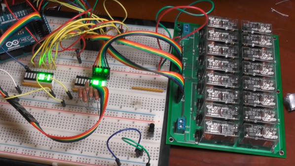
Using custom PCBs hosting banks of DPDT relays, he progresses from the basic AND and XOR gates to half adders and full adders, explaining how carry in and carry out works. Everything is modular, so four of his 4-bit adder cards eventually get together to form a 16-bit adder, which we assume will be used to build out a very noisy yet entertaining ALU. We’re looking forward to that and relay implementations of the flip-flops and other elements he’ll need for a full computer.

And pay no mind to our earlier dismissal of non-traditional computer projects. It’s worth checking out this discrete 7400 logic computer and this all-transistor build. They’re impressive too in their own way, if a bit quieter than [Clickety Clack]’s project.

Continue reading “Relay Computer Starts With An Adder That Makes A Racket”

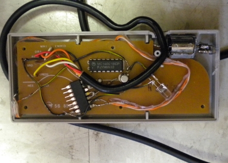
NES Controller Gets A Rumble Pak

Add some feedback to an original NES controller by making it vibrate. This feature is often known as Rumble Pak, a controller add-on for the Nintendo 64 which vibrated as a game feature. This version adds a small DC motor (in the upper right) with a screw soldered off-center to the motor shaft.

[Andy Goetz] and his friend built this as a robot controller, taking advantage of the latch and clock pins. Normally, nothing happens while both pins are held high, a signal that they easily patched into using an AND gate. This is actually a neat find, as the addition of an internal microcontroller could add bi-directional communication when the latch is high and the clock is strobed.