Learning About Capacitors By Rolling Your Own Electrolytics

Ever wonder what’s inside an electrolytic capacitor? Many of us don’t, having had at least a partial glimpse inside after failure of the cap due to old age or crossed polarity. The rest of us will have to rely on this behind-the-scenes demo to find out what’s inside those little aluminum cans.

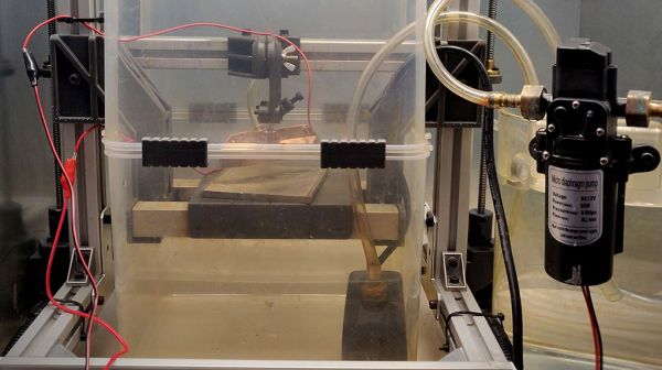
Perhaps unsurprisingly, it’s more aluminum, at least for the electrolytics [Denki Otaku] rolled himself at the Nippon Chemi-Con R&D labs. Interestingly, both the anode and cathode start as identical strips of aluminum foil preprocessed with proprietary solutions to remove any oils and existing oxide layers. The strips then undergo electrolytic acid etching to create pits to greatly increase their surface area. The anode strips then get anodized in a solution of ammonium adipate, an organic acid that creates a thin aluminum oxide layer on the strip. It’s this oxide layer that actually acts as the dielectric in electrolytic capacitors, not the paper separator between the anode and cathode strips.

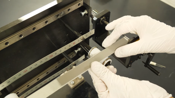
Winding the foils together with the paper separator is pretty straightforward, but there are some neat tricks even at the non-production level demonstrated here. Attachment of lead wires to the foil is through a punch and crimp operation, and winding the paper-foil sandwich is actually quite fussy, at least when done manually. No details are given on the composition of the electrolyte other than it contains a solvent and an organic acid. [Denki] took this as an invitation to bring along his own electrolyte: a bottle of Coke. The little jelly rolls get impregnated with electrolyte under vacuum, put into aluminum cans, crimped closed, and covered with a heat-shrink sleeve. Under test, [Denki]’s hand-rolled caps performed very well. Even the Coke-filled caps more or less hit the spec on capacitance; sadly, their ESR was way out of whack compared to the conventional electrolyte.

There are plenty more details in the video below, although you’ll have to pardon the AI voiceover as it tries to decide how to say words like “anode” and “dielectric”; it’s a small price to pay for such an interesting video. It’s a much-appreciated look at an area of the industry that few of us get to see in detail.

Continue reading “Learning About Capacitors By Rolling Your Own Electrolytics”

A Loving Look Inside Vacuum Fluorescent Displays

Everyone knows we’re big fans of displays that differ from the plain old flat-panel LCDs that seem to adorn most devices these days. It’s a bit boring when the front panel of your widget is the same thing you stare at hour after hour while using your phone. Give us the chunky, blocky goodness of a vacuum fluorescent display (VFD) any day of the week for visual interest and retro appeal.

From the video below, it seems like [Posy] certainly is in the VFD fandom too, rolling out as he does example after example of unique and complicated displays, mostly from audio equipment that had its heyday in the 1990s. In some ways, the video is just a love letter to the VFD, and that’s just fine with us. But the teardowns do provide some insights into how VFDs work, as well as suggest ways to tweak the overall look of a VFD.

For example, consider the classy white VFDs that graced a lot of home audio gear back in the day. It turns out, the phosphors used in those displays weren’t white, but closer to the blue-green color that VFDs are often associated with. But put a pink filter between the display and the world, and suddenly those turquoise phosphors look white. [Posy] does a lot of fiddling with the stock filters to change the look of his VFDs, some to good effect, others less so.

As for the internals of VFDs, [Posy]’s look at a damaged display reveals a lot about how they work. With a loose scrap of conductor shorting one of the cathodes inside the tube, the damaged VFD isn’t much to look at, and is beyond reasonable repair, but it’s kind of cool to examine the spring mechanisms that take up slack as the cathodes heat up and expand.

Thanks to [Posy] for this heartfelt look into the VFDs of yesterday. If you need more about how VFDs work, we’ve covered that before, too.

Continue reading “A Loving Look Inside Vacuum Fluorescent Displays”

Mining And Refining: Cobalt, The Unfortunately Necessary Metal

The story of humankind is largely a tale of conflict, often brought about by the uneven distribution of resources. For as long as we’ve been down out of the trees, and probably considerably before that too, our ancestors have been struggling to get what they need to survive, as often as not at the expense of another, more fortunate tribe. Food, water, land, it doesn’t matter; if They have it and We don’t, chances are good that there’s going to be a fight.

Few resources are as unevenly distributed across our planet as cobalt is. The metal makes up only a fraction of a percent of the Earth’s crust, and commercially significant concentrations are few and far between, enough so that those who have some often end up at odds with those who need it. And need it we do; what started in antiquity as mainly a rich blue pigment for glass and ceramics has become essential for important industrial alloys, high-power magnets, and the anodes of lithium batteries, among other uses.

Getting access to our limited supply of cobalt and refining it into a useful metal isn’t a trivial process, and unfortunately its outsized importance to technological society forces it into a geopolitical role that has done a lot to add to human misery. Luckily, market forces and new technology are making once-marginal sources viable, which just may help us get the cobalt we need without all the conflict.

Continue reading “Mining And Refining: Cobalt, The Unfortunately Necessary Metal”

3D-Printed Tooling Enables DIY Electrochemical Machining

When it comes to turning a raw block of metal into a useful part, most processes are pretty dramatic. Sharp and tough tools are slammed into raw stock to remove tiny bits at a time, releasing the part trapped within. It doesn’t always have to be quite so violent though, as these experiments in electrochemical machining suggest.

Electrochemical machining, or ECM, is not to be confused with electrical discharge machining, or EDM. While similar, ECM is a much tamer process. Where EDM relies on a powerful electric arc between the tool and the work to erode material in a dielectric fluid, ECM is much more like electrolysis in reverse. In ECM, a workpiece and custom tool are placed in an electrolyte bath and wired to a power source; the workpiece is the anode while the tool is the cathode, and the flow of charged electrolyte through the tool ionizes the workpiece, slowly eroding it.

The trick — and expense — of ECM is generally in making the tooling, which can be extremely complicated. For his experiments, [Amos] took the shortcut of 3D-printing his tool — he chose [Suzanne] the Blender monkey — and then copper plating it, to make it conductive. Attached to the remains of a RepRap for Z-axis control and kitted out with tanks and pumps to keep the electrolyte flowing, the rig worked surprisingly well, leaving a recognizably simian faceprint on a block of steel.

[Amos] admits the setup is far from optimized; the loop controlling the distance between workpiece and tool isn’t closed yet, for instance. Still, for initial experiments, the results are very encouraging, and we like the idea of 3D-printing tools for this process. Given his previous success straightening his own teeth or 3D-printing glass, we expect he’ll get this fully sorted soon enough.

Overdriving Vacuum Tubes And Releasing The Magic Light Within

We’ve all seen electronic components that have been coaxed into releasing their small amount of Magic Smoke, which of course is what makes the thing work in the first place. But back in the old times, parts were made of glass and metal and were much tougher — you could do almost anything to them and they wouldn’t release the Magic Smoke. It was very boring.

Unless you knew the secret of “red plating”, of course, which [David Lovett] explores in the video below. We’ve been following [David]’s work with vacuum tubes, the aforementioned essentially smokeless components that he’s putting to use to build a simple one-bit microprocessor. His circuits tend to drive tubes rather gently, but in a fun twist, he let his destructive side out for a bit and really pushed a few tubes to see what happens. And what happens is pretty dramatic — when enough electrons stream from the cathode to the anode, their collective kinetic energy heats the plate up to a cherry-red, hence the term “red plating”.

[David] selected a number of victims for his torture chamber, not all of which cooperated despite the roughly 195 volts applied to the plate. Some of the tubes, though, cooperated in spades, quickly taking on a very unhealthy glow. One tube, a 6BZ7 dual triode, really put on a show, with something getting so hot inside the tube as to warp and short together, leading to some impressive pyrotechnics. Think of it as releasing the Magic Light instead of the Magic Smoke.

Having seen how X-ray tubes work, we can’t help but wonder if [David] was getting a little bit more than he bargained for when he made this snuff film. Probably not — the energies involved with medical X-ray tubes are much higher than this — but still, it might be interesting to see what kinds of unintended emissions red-plating generates.

Continue reading “Overdriving Vacuum Tubes And Releasing The Magic Light Within”

State Of The Art For Nixies Gets A Boost From Dalibor Farny’s Supersize Prototype

Never one to pass up on a challenge, artisanal Nixie tube maker [Dalibor Farný] has been undertaking what he calls “Project H”, an enormous array of 121 Nixie tubes for an unnamed client. What’s so special about that? Did we mention that each Nixie is about the size of a sandwich plate?

Actually, we did, back in May when we first noted Project H in our weekly links roundup. At that time [Dalibor] had only just accepted the project, knowing that it would require inventing everything about these outsized Nixies from scratch. At 150 mm in diameter, these will be the largest Nixies ever made. The design of the tube is evocative of the old iconoscope tubes from early television history, or perhaps the CRT from an old oscilloscope.

Since May, [Dalibor] has done most of the design work and worked out the bugs in a lot of the internal components. But as the video below shows, he still has some way to go. Everything about his normal construction process had to be scaled up, so many steps, like the chemical treatment of the anode cup, are somewhat awkward. He also discovered that mounting holes in the cathodes were not the correct diameter, requiring some clench-worthy manual corrections. The work at the glassblower’s lathe was as nerve wracking as it was fascinating; every step of the build appears fraught with some kind of peril.

Sadly, this prototype failed to come together — a crack developed in the glass face of the tube. But ever the pro, [Dalibor] took it in stride and will learn from this attempt. Given that he’s reduced the art of the Nixie to practice, we’re confident these big tubes will come together eventually.

Continue reading “State Of The Art For Nixies Gets A Boost From Dalibor Farny’s Supersize Prototype”

Ambitious Homebrew X-Ray Machine Reveals What Lies Within

We’re not quite sure what to say about this DIY X-ray machine. On the one hand, it’s a really impressive build, with incredible planning and a lot of attention to detail. On the other hand, it’s a device capable of emitting dangerous doses of ionizing radiation.

In the end, we’ll leave judgment on the pros and cons of [Fran Piernas]’ creation to others. But let’s just say it’s probably a good thing that a detailed build log for this project was not provided. Still, the build video below gives us the gist of what must have taken an awfully long time and a fair amount of cash to pull off. The business end is a dental X-ray tube of the fixed anode variety. We’ve covered the anatomy and physiology of these tubes previously if you need a primer, but basically, they use a high voltage to accelerate electrons into a tungsten target to produce X-rays. The driver for the high voltage supply, which is the subject of another project, is connected to a custom-wound transformer to get up to 150V, and then to a voltage multiplier for the final boost to 65 kV. The tube and the voltage multiplier are sealed in a separate, oil-filled enclosure for cooling, wisely lined with lead.

The entire machine is controlled over a USB port. An intensifying screen converts the X-rays to light, and the images of various objects are quite clear. We’re especially impressed by the fluoroscopic images of a laptop while its hard drive is seeking, but less so with the image of a hand, presumably [Fran]’s; similar images were something that [Wilhelm Röntgen] himself would come to regret.

Safety considerations aside, this is an incredibly ambitious build that nobody else should try. Not that it hasn’t been done before, but it still requires a lot of care to do this safely.

Continue reading “Ambitious Homebrew X-Ray Machine Reveals What Lies Within”