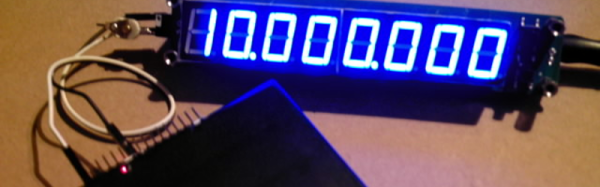
[Paulie] over on the EEVBlog forums picked up an inexpensive frequency counter on eBay and realized it was just a little bit off. As a result, he decided to build a frequency standard. His build wound up costing him about $3 and he shared the design and the software for it.
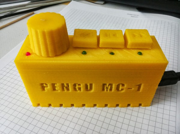
The hardware design is very simple: a TCXO (also from eBay), an ATMega8, a pushbutton, and a AA battery with DC to DC converter to power the whole thing. The software does all the work, providing frequencies from 10MHz down to a few hundred hertz (including some common audio test frequencies).
If you haven’t worked with a TCXO before, it is a crystal oscillator that includes a temperature compensation circuit to pull the crystal frequency up or down depending on temperature. Although crystal oscillators are pretty accurate already, adding this temperature compensation improves accuracy over the design temperature dramatically (typically, 10 to 40 times better than a naked crystal oscillator). If you want to learn more about TCXOs, here’s a good write-up.
A TCXO isn’t as good as an OCXO (where the first O stands for Oven). However, OCXOs cost more, are larger, and drain batteries (after all, it is running an oven). You can even hack your own OCXO, but it is going to cost more than $3.
If you want to see the real guts of one TCXO, check out the video.