A Look Inside A 70-GHz Electromechanical Attenuator

It might not count as “DC to daylight,” but an electromechanical attenuator that covers up to 70 GHz is pretty close, and getting a guided tour of its insides is quite a treat.

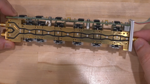
Perhaps unsurprisingly, this one comes to us from [Shahriar] at “The Signal Path,” where high-end gear most of us never get a chance to work with goes for one last hurrah after it releases the magic smoke. And indeed, that appears to be exactly what happened to the Rohde & Schwarz 75 dB step attenuator, a part that may have lived in the front end of one of their spectrum analyzers. As one would expect from such an expensive component, the insides have some pretty special engineering. The signal is carried through the five attenuation stages on a narrow strip of copper. Each stage uses a solenoid to move the strip between either a plain conductor or a small Pi pad with a specified attenuation. The attention to detail inside the cavity is amazing, with great care taken to maintain the physical orientation of the stripline to prevent impedance mismatches and unwanted reflections.

The Pi pads themselves are fascinating, too, especially under [Shahriar]’s super-duper microscope. All of them were destructively removed from the cavity before getting to him, but it’s still pretty clear what’s going on. That’s especially true with the 5-dB pad, which bears clear signs of the overload that brought on the demise of the whole attenuator. We suppose a repair would have been feasible if it had been just the one pad that needed replacement, but with all of them broken, it’s off to the scrap bin. Or to the recycler — there appears to be plenty of gold in there.

We thought this was a fantastic look under the covers of an exquisitely engineered part. Too bad it didn’t rate the [Shahriar] X-ray treatment, as this multimeter repair or this 60-GHz phased array did. Oh, well — maybe next time.

Continue reading “A Look Inside A 70-GHz Electromechanical Attenuator”

Retrotechtacular: Crash Testing Truck Attenuators, For Science

There are those among us who might bristle at something from the early 1980s qualifying for “Retrotechtacular” coverage, but it’s been more than 40 years since the California Department of Transportation’s truck-mounted attenuators crash testing efforts, so we guess it is what it is.

If you’re worried that you have no idea what a “truck-mounted attenuator” might be, relax — you’ve probably seen these devices attached to the backs of trucks in highway work zones. They generally look like large boxes attached to frames at the rear of the truck which are intended to soften the blow should a car somehow not see the giant orange truck covered with flashing lights and drive into the rear of it at highway speeds. Truck-mounted attenuators are common today, but back in 1982 when this film was produced, the idea was still novel enough to justify crash-testing potential designs.

Continue reading “Retrotechtacular: Crash Testing Truck Attenuators, For Science”

Wien Bridge Oscillator Drives Distortion Into The Floor

It’s not often that a single photo can tell you pretty much everything you need to know about a project, but the spectrum analyzer screenshot nearby is the perfect summary of this over-the-top low-distortion audio oscillator build. But that doesn’t mean there’s not a ton of interesting stuff going on with this one, so buckle up.

One spike at the fundamental and not much more.

The project is by [Basin Street Design], who doesn’t really offer much by way of inspiration for this undertaking, nor a discussion on what this will be used for. But the design goals are pretty clear: build an oscillator with as little distortion as possible across the audio frequency range.

The basic circuit is the well-known Wien bridge oscillator where the R-C pairs are switched in and out of the feedback loop to achieve frequency range control. This was accomplished with rotary switches rebuilt from their original configuration in a Heathkit IG-18 sine/square wave generator, a defunct instrument that was gutted and used as an enclosure for this build. There are a lot of other treats here, too, like the automatic gain control (AGC) that uses a homebrew voltage-controlled resistor made from an incandescent lamp and a cadmium sulfide photoresistor glued inside a piece of brake line, and an output attenuator made from discrete resistors that drops the output in 10 dB steps while maintaining an overall 75-Ohm impedance.

But at the end of the day, it all comes down to that single spike on the spectrum analyzer, with no apparent harmonics. To make sure there wasn’t something hiding down in the noise, [Basin Street] added a notch filter to lower the fundamental by 60 dB, allowing the spectrum analyzer sensitivity to be cranked way up. Harmonics were visible, but so far down into the noise — as low as -115 dBc — that it’s hardly worth mentioning.

There’s a lot more detail in this one, so dive in and enjoy. If you want another take on Wien bridge circuits, check out this recent LM386-based oscillator. Just don’t expect such low distortion with that one.

A Modern Take On A Piece Of Old Test Equipment

The HP 11947A is something of a footnote in the back catalogue of Hewlett Packard test equipment. An attenuator and limiter with a bandwidth in the megahertz rather than the gigahertz. It’s possible that few laboratories have much use for one in 2019, but it does have one useful property: a full set of schematics and technical documentation. [James Wilson] chose the device as the subject of a clone using surface mount devices.

The result is very satisfyingly within spec, and he’s run a battery of tests to prove it. As he says, the HP design is a good one to start with.   As a device containing only passive components and with a maximum frequency in the VHF range this is a project that makes a very good design exercise for anyone interested in RF work or even who wishes to learn a bit of RF layout. At these frequencies there are still a significant number of layout factors that can affect performance, but the effect of conductor length and  stray capacitance is less than the much higher frequencies typically used by wireless-enabled microcontrollers.

A DIY Step Attenuator, By Gluing Together Two Smaller Ones

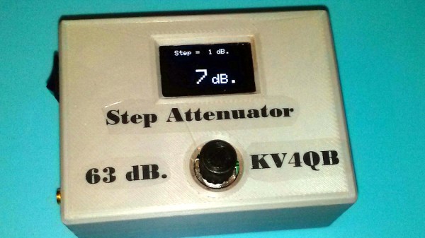
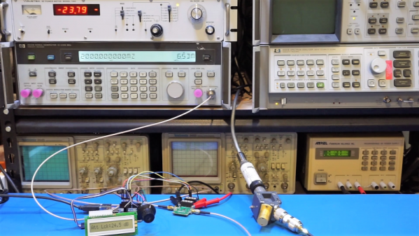
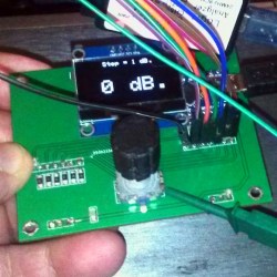
In the RF world, attenuators are a useful test and measurement tool. Variable units that can apply different levels of attenuation in discrete steps are even better. [DuWayne] made a 63 dB step attenuator by putting two smaller units in series, with an Arduino Nano in control of them. With a 3D printed enclosure and OLED for feedback, the device is easily adjusted with a single rotary encoder. There was even room to add a micro USB plug for recharging the power supply.

The two smaller digital attenuators [DuWayne] used are essentially breakout boards for the PE4302 digital RF attenuator, and cheaply available from the usual overseas sources. They are capable of up to 31.5 dB of attenuation in 0.5 dB steps, and by using two in series (and controlling them in parallel) [DuWayne] gets a range of up to 63 dB. The design files can be downloaded from a Dropbox share for the project, should you wish to try any of it for yourself.

Are you interested in RF and maybe software defined radio (SDR)? We’ve covered all the stuff you’ll need to get started with an inexpensive RTL-SDR, and sooner or later you may find yourself in need of [Dan Maloney]’s info on cheap and effective dummy loads.

Digital Attenuator Goes From Manual To Arduino Control

[Kerry Wong] comes across the coolest hardware, and always manages to do something interesting with it. His widget du jour is an old demo board for a digital RF attenuator chip, which can pad a signal in discrete steps according to the settings of some DIP switches. [Kerry]’s goal: forget the finger switch-flipping and bring the attenuator under Arduino control.

As usual with his videos, [Kerry] gives us a great rundown on the theory behind the hardware he’s working with. The chip in question is an interesting beast, an HMC624LP4E from Hittite, a company that was rolled into Analog Devices in 2014. The now-obsolete device is a monolithic microwave integrated circuit (MMIC) built on a gallium arsenide substrate rather than silicon, and attenuates DC to 6-GHz signals in 64 steps down to -31.5 dBm. After a functional check of the board using the DIP switches, he whipped up a quick Arduino project to control the chip with its built-in serial interface. It’s just a prototype for now, but spinning the encoder is a lot handier than flipping switches, and once this is boxed up it’ll make a great addition to [Kerry]’s RF bench.

If this video puts you in an RF state of mind, check out some of [Kerry]’s other videos, like this one about temperature-compensated crystal oscillators, or the mysteries of microwave electronics.

Continue reading “Digital Attenuator Goes From Manual To Arduino Control”

Pi Network Attenuators: Impedance Matching For The Strong Of Signal

If you catch a grizzled old radio amateur propping up the bar in the small hours, you will probably receive the gravelly-voiced Wisdom of the Ancients on impedance matching, antenna tuners, and LC networks. Impedance at RF, you will learn, is a Dark Art, for which you need a lifetime of experience to master. And presumably a taste for bourbon and branch water, to preserve the noir aesthetic.

It’s not strictly true, of course, but it is the case that impedance matching at RF with an LC network can be something of a pain. You will calculate and simulate, but you will always find a host of other environmental factors getting in the way when it comes down to achieving a match. Much tweaking of values ensues, and probably a bit of estimating just how bad a particular voltage standing wave ratio (VSWR) can be for your circuit.

Continue reading “Pi Network Attenuators: Impedance Matching For The Strong Of Signal”