Milling a PCB at home is a great way to save some time and money if you are making one-off circuit boards. There is a downside though, it’s a little tough. Sure, just export your Eagle design to CNC-Machine-understandable g-code and fire up your mill…. well, it’s not that easy.
The copper on a PCB blank can be anywhere from about 0.001 to 0.006 inches thick. When milling a board the ideal situation is to mill just deep enough to get through the copper but not cut too deep into the fiberglass backer board. Cutting too deep can weaken the board, break a bit, or in an extreme case, cut through the entire board.
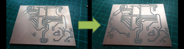
Shallow cuts can result in another problem, inconsistent cut depth over the surface of the board. Check out the left photo above. The traces on the left side of the board appears to have just faded away. This happened because the circuit board was not flat. The side where the traces are missing from is lower than the other so the tool bit is not able to reach that part of the board. Since an ideal depth of cut is about 0.010 inches, even a very small amount of waviness or out of flatness can cause a serious problem in the milling process. If you have a hard time picturing what 0.010 inches is, think the thickness of two pieces of paper, it’s not a lot. There are two main contributors to the flatness problem; the PCB board and/or the machine’s bed. If the bed is not flat, the PCB won’t be. Even if the bed is flat, the PCB may be warped or bent.
PCB fabrication enthusiast [daedelus] had this exact problem, and in true hacker fashion, decided to do something about it. He created a software program called AutoLeveller that takes a g-code file and adds a probing section to the beginning before the milling operation. When the modified g-code file is run on the CNC Machine, it first probes the surface of the PCB in a grid pattern and maps the flatness variation of the PCB’s surface. Then, when running the program, it adjusts the height of the tool bit on the fly so that the actual depth of cut is consistent over the entire board, regardless of how flat or not it is. The result is a clean and usable PCB on the first try.
There is one catch: the Machine Control Software has to be set up to accept a probe. This is easy to do if communicating to the CNC Machine via a computers parallel port. An input pin on the parallel port is pulled high with a resistor and connected electrically to the PCB board. The tool spindle is grounded with a clip lead. When the tool touches the board, the input pin is pulled low and the Machine Control Software records the tool height for that specific XY position.


