Score Big Against Boredom With Tabletop Bowling

Bowling has been around since ancient Egypt and continues to entertain people of all ages, especially once they roll out the fog machine and hit the blacklights. But why pay all that money to don used shoes and drink watered-down beer? Just build a tabletop bowling alley in your spare time and you can bowl barefoot if you want.

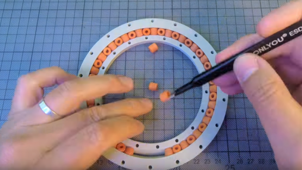
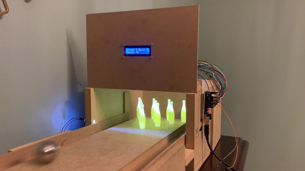
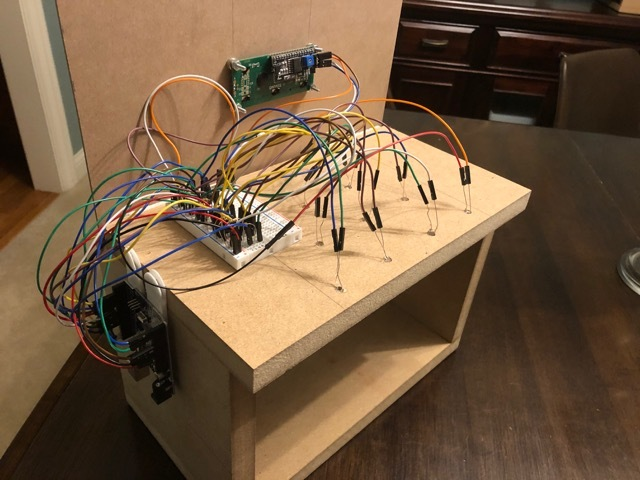
Those glowing pins aren’t just for looks — the LEDs underneath them are part of the scoring system. Whenever a pin is knocked out of its countersunk hole, the LED underneath is exposed and shines its light on a corresponding light-dependent resistor positioned overhead. An Arduino Uno keeps track of of the frame, ball number, and score, and displays it on an LCD.

The lane is nearly six feet long, so this is more like medium-format bowling or maybe even skee-bowling. There are probably a number of things one could use for balls, but [lainealison] is using large ball bearings. Roll past the break to see it in action, but don’t go over the line!

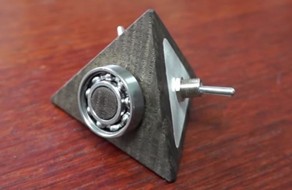
Can’t keep your balls out of the gutter? Build a magic ball and make all wishful leaning more meaningful as you steer it down the lane with your body.

Continue reading “Score Big Against Boredom With Tabletop Bowling”

Giant Bearing Is At The Heart Of A Camera Mount

We bet you have all some cool part in your bin that is just gnawing at you to build something cool. That doodad, possibly from a garage sale, surplus store, or clearance rack deserves a project fitting of its near-infinite potential. [isaac879] finally marries a giant ball bearing with his passion for photography in the form of a pan-tilt camera mount for his Canon DSLR. The problem with tossing your golden-ticket part into a project is that not everyone has a MacGuffin, or a brand new one might be bank-breakingly expensive, so he does us a favor and makes a drop-in replacement that you can print and fill with 6mm brass bbs. This sort of thing is why we love hackers.

The camera mount has the features we expect to see in a robust stepper mount, such as infinite spinning, time delay, and an Xbox controller interface. Inside the base is the industrial bearing or its plastic replica, and that wide base won’t be tipping over anytime soon. Gearing all around is of the herringbone style, of the type you find in classroom pencil sharpeners because they transfer power smoothly. Speaking of things going smoothly, we enjoyed his assembly montage where every part fits together perfectly and there is not a naughty word to be uttered. Just like real life.

If you like homemade bearings, check out this slew bearing that looks like it was made with Perler beads, and we have a self-aligning camera tripod mount for the photography buffs.

Continue reading “Giant Bearing Is At The Heart Of A Camera Mount”

SandBot Happily And Tirelessly Rolls Patterns In Sand

The patience and precision involved with drawing geometric patterns in sand is right up a robot’s alley, and demonstrating this is [rob dobson]’s SandBot, a robot that draws patterns thanks to an arm with a magnetically coupled ball.

SandBot, SCARA version. The device sits underneath a sand bed, and a magnet (seen at the very top at the end of the folded “arm”) moves a ball bearing through sand.

SandBot is not a cartesian XY design. An XY frame would need to be at least as big as the sand table itself, but a SCARA arm can be much more compact. Sandbot also makes heavy use of 3D printing and laser-cut acrylic pieces, with no need of an external frame.

[rob]’s writeup is chock full of excellent detail and illustrations, and makes an excellent read. His previous SandBot design is also worth checking out, as it contains all kinds of practical details like what size of ball bearing is best for drawing in fine sand (between 15 and 20 mm diameter, it turns out. Too small and motion is jerky as the ball catches on sand grains, and too large and there is noticeable lag in movement.) Design files for the SCARA SandBot are on GitHub but [rob] has handy links to everything in his writeup for easy reference.

Sand and robots (or any moving parts) aren’t exactly a natural combination, but that hasn’t stopped anyone. We’ve seen Clearwalker stride along the beach, and the Sand Drawing Robot lowers an appendage to carve out messages in the sand while rolling along.

Big Slew Bearings Can Be 3D Printed

Consider the humble ball bearing. Ubiquitous, useful, and presently annoying teachers the world over in the form of fidget spinners. One thing ball bearings aren’t is easily 3D printed. It’s hard to print a good sphere, but that doesn’t mean you can’t print your own slew bearings for fun and profit.

As [Christoph Laimer] explains, slew bearings consist of a series of cylindrical rollers alternately arranged at 90° angles around an inner and outer race, and are therefore more approachable to 3D printing. Slew bearings often find application in large, slowly rotating applications like crane platforms or the bearings between a wind turbine nacelle and tower. In the video below, [Christoph] walks us through his parametric design in Fusion 360; for those of us not well-versed in the app, it looks a little like magic. Thankfully he has provided both the CAD files and a selection of STLs for different size bearings.

[Christoph] is no stranger to complex 3D-printable designs, like his recent brushless DC motor or an older clock build. The clock is cool, but the bearings and motors really get us — we’ll need such designs to get to self-replicating machines.

Continue reading “Big Slew Bearings Can Be 3D Printed”

Fidget Pyramid With Help From A 2500 Pound Robot

Depending on whom you ask, fidgeting is an unsightly habit or a necessity for free-form ideation. Fan of the latter hypothesis? Well, why aren’t you making yourself a fidget pyramid?

[lignum] sculpted his fidget toy out of a chunk of 2000 year old bog-oak using hand tools and a little precision help from a Kuka KR 150 industrial robot arm. A push button, a toggle switch, a ball-bearing, and a smooth side provide mindless distraction on this piece.

Two plates of 1.5mm aluminium — also cut using the robot arm — are used to attach the button and toggle to the tetrahedron, while the ball bearing is pushed onto a cylindrical protrusion left during the cutting process for the purpose. The build video makes it look easy.

Continue reading “Fidget Pyramid With Help From A 2500 Pound Robot”

Mastering Ball Screws

Most inexpensive 3D printers use a type of lead screw to move some part of the printer in the vertical direction. A motor turns a threaded rod and that causes a nut to go up or down. The printer part rides on the nut. This works well, but it is slower than other drive mechanisms (which is why you don’t often see them on the horizontal parts of a printer). Some cheap printers use common threaded rod, which is convenient, but prone to bad behavior since the rods are not always straight, the threads are subject to backlash, and the tolerances are not always the best.

More sophisticated printers use ACME threaded rod or trapezoidal threaded rods. These are made for this type of service and have thread designs that minimize things like backlash. They typically are made to more exacting standards, too. Making the nut softer than the rod (for example, brass or Delrin) is another common optimization.

However, when lead screws aren’t good enough, mechanical designers turn to ball screws. In principle, these are very similar to lead screws but instead of a nut, there is a race containing ball bearings that moves up and down the screw. The ball bearings lead to less friction.

Misumi recently posted a few blog articles about ball screws. Some of the information is basic, but it also covers preloading and friction. Plus they are promising future articles to expand on the topic. If you prefer to watch a video, you might enjoy the one below.

Continue reading “Mastering Ball Screws”

CNC Clock Mills Itself, Displays The Time

[Christian] wrote and sells some CAM/CNC controller software. We’re kinda sticklers for open source, and this software doesn’t seem to be, so “meh”. But what we do like is the Easter egg that comes included: the paths to mill out the base for a clock, and then the codes to move steel ball-bearings around to display the time.

Of course we’d like to see more info (more, MORE, MOAR!) but it looks easy enough to recreate. We could see redesigning this with marbles and a vacuum system, for instance. The seats for the ball bearings don’t even need to be milled out spheres. You could do this part with a drill press. Who’s going to rebuild this for their 3D printer? You just have to make sure that the machine is fast enough to move the balls around within one minute.

Continue reading “CNC Clock Mills Itself, Displays The Time”