Improving Cheap Ball Screws

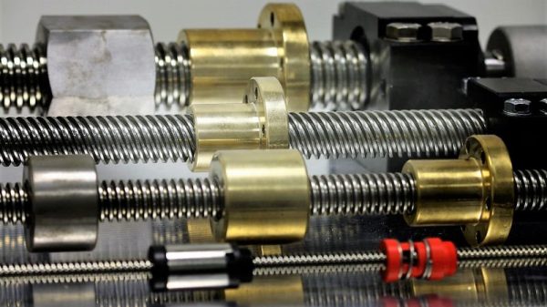
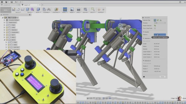
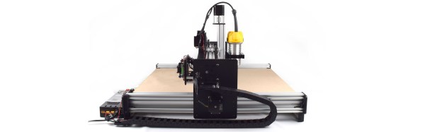
Most 3D printers use leadscrews for at least one axis. These are simple devices that are essentially a steel screw thread and a brass nut that travels on it. However, for maximum precision, you’d like to use a ball screw. These are usually very expensive but have many advantages over a leadscrew. [MirageC] found cheaper ball screws but, since they were inexpensive, they had certain limitations. He designed a simple device that improves the performance of these cheap ball screws.

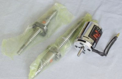
Superficially, a ball screw looks like a leadscrew with an odd-looking thread. However, the nut is very different. Inside the nut are ball bearings that fit in the grooves and allows the nut to spin around with much less friction. A special path collects the ball bearings and recirculates them to the other side of the nut. In general, ball screws are very durable, can handle higher loads and higher speeds, and require less maintenance. Unlike leadscrews, they are more expensive and are usually quite rigid. They are also a bit noisier, though.

Ball screws are rated C0 to C10 precision where C10 is the least accurate and the price goes up — way up — with accuracy. [MirageC] shows how cheaper ball screws can be rolled instead of precision ground. These screws are cheaper and harder, but exhibit more runout than a precision screw.

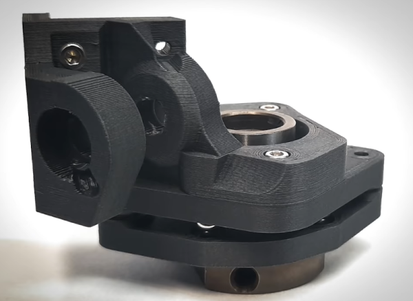
This runout caused wobble during 3D printing that was immediately obvious on the prints. Using a machinist’s dial gauge, [MirageC] found the screws were not straight at all and that even a relatively poor C7 ball screw would be more precise.

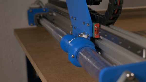
The solution? A clever arrangement of 3D printed parts. ball bearings, and magnets. The device allows the nut to move laterally without transmitting it to the print bed. It is a clever design and seems to work well.

Continue reading “Improving Cheap Ball Screws”

Plastic Strips Protect Ball Screws On This Homebrew CNC Router

It’s a fact of life for CNC router owners — swarf. Whether it’s the fine dust from a sheet of MDF or nice fat chips from a piece of aluminum, the debris your tool creates gets everywhere. You can try to control it at its source, but swarf always finds a way to escape and cause problems.

Unwilling to deal with the accumulation of chips in the expensive ball screws of his homemade CNC router, [Nikodem Bartnik] took matters into his own hands and created these DIY telescopic ball screw covers. Yes, commercial ball screw covers are available, but they are targeted at professional machines, and so are not only too large for a homebrew machine like his but also priced for pro budgets. So [Nikodem] recreated their basic design: strips of thin material wound into a tight spring that forms a tube that can extend and retract. The first prototypes were from paper, which worked but proved to have too much friction. Version 2 was made from sheets of polyester film, slippery enough to get the job done and as a bonus, transparent. They look pretty sharp, and as you can see in the video below, seem to perform well.

It’s nice to see a build progress to the point where details like this can be addressed. We’ve been following [Nikodem]’s CNC build for years now, and it really has come a long way.

Continue reading “Plastic Strips Protect Ball Screws On This Homebrew CNC Router”

Steel Tubes And Ground Plates Form The Skeleton Of This DIY Vertical CNC Mill

If you’re going to do it yourself, you might as well outdo yourself. That seems to be the thinking behind this scratch-built CNC mill, and it’s only just getting started.

According to [Kris Temmerman], the build will cost about $10,000 by the time he’s done. So it’s not cheap, and a personal CNC from Tormach can be had for less, but that’s missing the point entirely. [Kris] built most of the structural elements for the vertical mill from cheap, readily available steel tubing, of the kind used for support columns in commercial buildings. Mounted to those are thick, precision-ground steel plates, which eat up a fair fraction of the budget. Those in turn hold 35 mm linear bearings and ball screws for the three axes, each powered by a beefy servo. The spindle is a BT30 with a power drawbar, belt-driven by an external motor that [Kris] doesn’t share the specs on, but judging from the way it flings chips during the test cut in the video below, we’d say it’s pretty powerful.

There’s still plenty to do, not least of which is stiffening the column; perhaps filling it with epoxy granite would do the trick? But it sure looks like [Kris] is building a winner here, and if he keeps the level of craftsmanship up going forward, he’ll have a top-quality machine on his hands.

Continue reading “Steel Tubes And Ground Plates Form The Skeleton Of This DIY Vertical CNC Mill”

Mechanisms: Lead Screws And Ball Screws

Translating rotary motion to linear motion is a basic part of mechatronic design. Take a look at the nearest 3D-printer or CNC router — at least the Cartesian variety — and you’ll see some mechanism that converts the rotation of the the motor shafts into the smooth linear motion needed for each axis.

Hobby-grade machines are as likely as not to use pulleys and timing belts to achieve this translation, and that generally meets the needs of the machine. But in some machines, the stretchiness of a belt won’t cut it, and the designer may turn to some variety of screw drive to do the job.

Continue reading “Mechanisms: Lead Screws And Ball Screws”

Homebrew Linear Actuators Put The Moves On This Motion Simulator

Breaking into the world of auto racing is easy. Step 1: Buy an expensive car. Step 2: Learn how to drive it without crashing. If you’re stuck at step 1, and things aren’t looking great for step 2 either, you might want to consider going with a virtual Porsche or Ferrari and spending your evenings driving virtual laps rather than real ones.

The trouble is, that can get a bit boring after a while, which is what this DIY motion simulator platform is meant to address. In a long series of posts with a load of build details, [pmvcda] goes through what he’s come up with so far on this work in progress. He’s building a Stewart platform, of the type we’ve seen before but on a much grander scale. This one will be large enough to hold a race car cockpit mockup, which explains the welded aluminum frame. We were most interested in the six custom-made linear actuators, though. Aluminum extrusions form the frame holding BLDC motor, and guide the nut of a long ball screw. There are a bunch of 3D-printed parts in the actuators, each of which is anchored to the frame and to the platform by simple universal joints. The actuators are a little on the loud side, but they’re fast and powerful, and they’ve got a great industrial look.

If car racing is not your thing and you’d rather build a full-motion flight simulator, here’s one that also uses DIY actuators.

Continue reading “Homebrew Linear Actuators Put The Moves On This Motion Simulator”

James Bruton's openDog inverse kinematics

[James Bruton] Is Making A Dog: OpenDog Project

There was a time when a two-legged walking robot was the thing to make. But after seeing years of Boston Dynamic’s amazing four-legged one’s, more DIYers are switching to quadrupeds. Now we can add master DIY robot builder [James Bruton] to the list with his openDog project. What’s exciting here is that with [James’] extensive robot-building background, this is more like starting the challenge from the middle rather than the beginning and we should see exciting results sooner rather than later.

James' motor and ball screws
James’ motor and ball screws

Thus far [James] has gone through the planning stage, having iterated through a few versions using Fusion 360, and he’s now purchased the parts. It’s going to be about the same size as Boston Robotic’s SpotMini and uses three motors for each leg. He considered going with planetary gearboxes on the motors but experienced a certain amount of play, or backlash, with them in his BB-9E project so this time he’s going with ball screws as he did with his exoskeleton. (Did we mention his extensive background?)

Each leg is actually made up of an upper and lower leg, which means his processing is going to have to include some inverse kinematics. That’s where the code decides where it wants the foot to go and then has to compute backwards from there how to angle the legs to achieve that. Again drawing from experience when he’s done it the hard way in the past, this time he’s designed the leg geometry to make those calculations easy. Having written up some code to do the calculations, he’s compared the computed angles with the measurements he gets from positioning the legs in Fusion 360 and found that his code is right on. We’re excited by what we’ve seen so far and bet it’ll be standing and walking in no time. Check out his progress in the video below.

Continue reading “[James Bruton] Is Making A Dog: OpenDog Project”

Adding Screws To A DIY CNC Machine

When it comes to CNC machines, your SureFine has screws on its axes, and the Bodgeport does too. A shopbot has an amazing rack gear system, but when you start to dig into the small CNC routers available for under $2,000, you’ll only find belts moving a router back and forth. This isn’t to say belts won’t work — you can create a fine CNC machine with bits of rubber. However, belts stretch, they wear out, and if you want more precision screws and racks are the way to go.

The WorkBee CNC machine is the first desktop CNC router we’ve seen that uses screws instead of belts. It’s a project on OpenBuilds, and a reasonably well-configured machine is now available from ooznest for about £1,700 ($2,200 USD), or just a bit more than other CNC routers that consist of a Dewalt router and some aluminum extrusion.

The WorkBee CNC is based on the OX CNC machine, another cartesian router machine built around the OpenBuilds aluminum extrusion. The OX, while a fine machine for DIY tinkerers, uses belts. The WorkBee trades them out for screws, and should gain better accuracy, much lower maintenance, and deeper cuts. Screws are slower, yes, but do you really need that much acceleration when routing a thick piece of wood?