Reballing And A Steady Hand Makes A Raspberry Pi 800

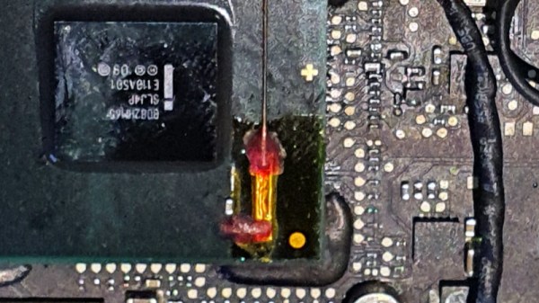
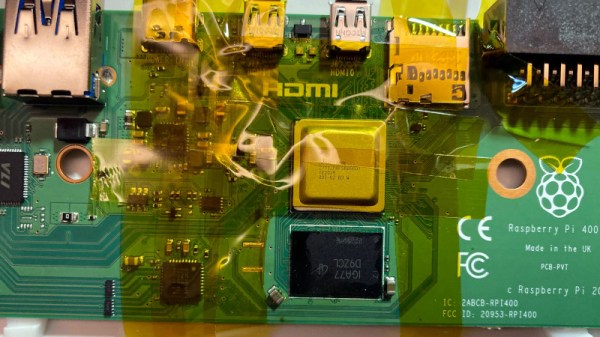
The all-in-one Raspberry Pi 400 computer is a capable device, but those seeking its maximum power may be disappointed by its 4 GB of memory. When the Pi 4 and Compute Module 4 have double that figure, surely the Pi 400 could catch up! A reddit user called [Pi800] rose to the challenge by replacing the 4 GB chip from the Pi 400 with the 8 GB chip from a Pi Compute Module, resulting in the so-called Pi 800, a working 8 GB all-in-one Pi.

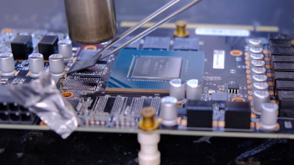
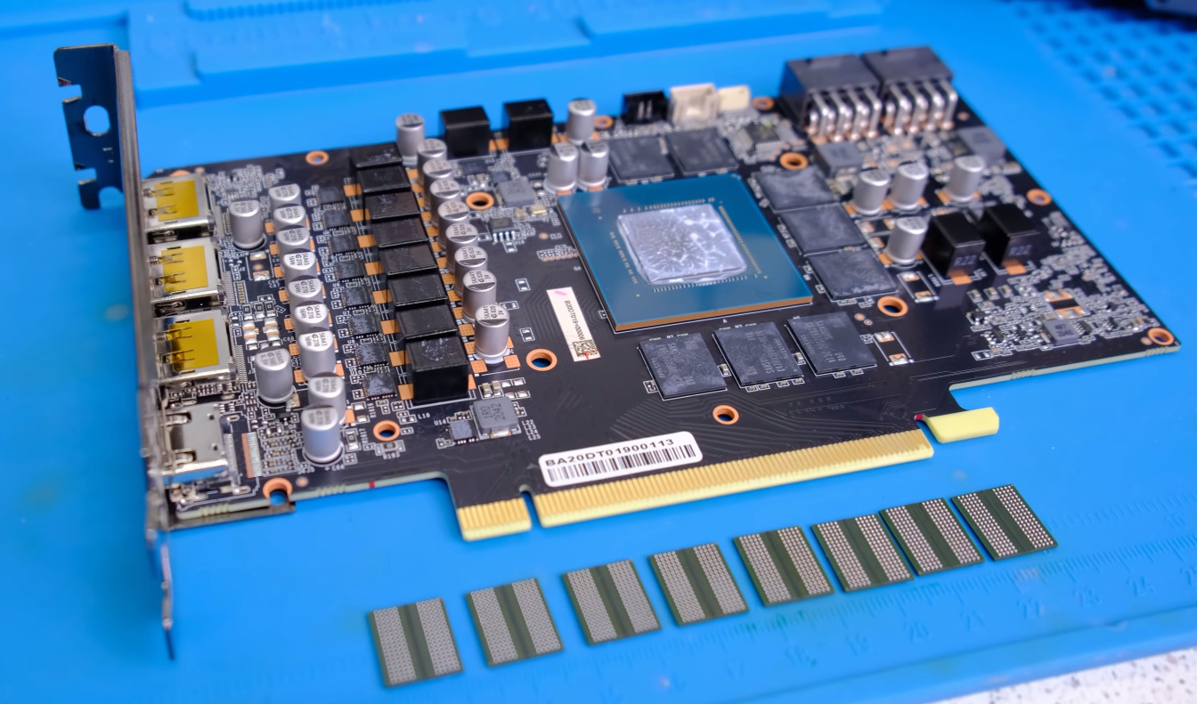
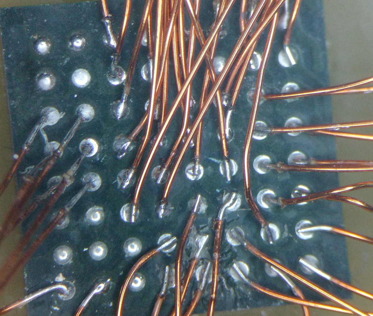
As a piece of work it’s a deceptively straightforward yet extremely fiddly piece of soldering that requires a steady hand for even the most skilled of solderers. What takes it beyond the norm though is the reballing process. A ball-grid-array chip has a grid of small balls of solder on its underside that make the contacts, and these melt when it is soldered so require replacement before reworking. This is normally done with a template of carefully aligned holes to line up balls of solder in a stream of hot air, but lacking the template in this case the job was done by hand, laboriously ball by ball. A soldering task we’d hesitate to take on ourselves, so we’re impressed.

The result is an 8 GB all-in-one Pi, and it’s honestly not beyond the realms of possibility that an official version of this mod could be a future Raspberry Pi product. Perhaps we’ll wait for that, but should you be impatient then at least it’s possible to roll your own. It’s certainly not the first BGA memory swap we’ve brought you.

Video Ram Transplant Doubles RTX 3070 Memory To 16 GB

Making unobtainium graphics cards even more unobtainable, [VIK-on] has swapped out the RAM chips on an Nvidia RTX 3070. This makes it the only 3070 the world to work with 16 GB.

If this sounds familiar, it’s because he tried the same trick with the RTX 2070 back in January but couldn’t get it working. When he first published the video showing the process of desoldering the 3070’s eight Hynix 1 GB memory chips and replacing them with eight Samsung 2 GB chips he hit the same wall — the card would boot and detect the increased RAM, but was unstable and would eventually crash. Helpful hints from his viewers led him to use an EVGA configuration GUI to lock the operating frequency which fixed the problem. Further troubleshooting (YouTube comment in Russian and machine translation of it) showed that the “max performance mode” setting in the Nvidia tool is also a solution to stabilize performance.

The new memory chips don’t self-report their specs to the configuration tool. Instead, a set of three resistors are used to electronically identify which hardware is present. The problem was that [VIK-on] had no idea which resistors and what the different configurations accomplished. It sounds like you can just start changing zero Ohm resistors around to see the effect in the GUI, as they configure both the brand of memory and the size available. The fact that this board is not currently sold with a 16 GB option, yet the configuration tool has settings for it when the resistors are correctly configured is kismet.

So did it make a huge difference? That’s difficult to say. He’s running some benchmarks in the video, both Unigine 2 SuperPosition and 3DMark Time Spy results are shown. However, we didn’t see any tests run prior to the chip swap. This would have been the key to characterizing the true impact of the hack. That said, reworking these with a handheld hot air station, and working your way through the resistor configuration is darn impressive no matter what the performance bump ends up being.

Continue reading “Video Ram Transplant Doubles RTX 3070 Memory To 16 GB”

BGA Soldering And Inspection

If you want to build cool things these days, you’ve probably had to master surface mount electronics. However, for many people, ball grid array (BGA) is still intimidating. Have a look at [VoltLog’s] video about his techniques for soldering BGA and inspecting that you managed to do it right.

He’s got quite a few tips about things like surface finish and flux selection. It looks easy when he does it. Of course, having a good PCB with good registration markings will help too.

Continue reading “BGA Soldering And Inspection”

Thinking About Creating A Raspberry Pi Replacement?

If you’ve ever wanted to try your hand at creating a Raspberry Pi-like board for yourself, you should check out [Jay Carlson’s] review of 10 different Linux-capable SoCs. Back in the 1960s, a computer was multiple refrigerator-sized boxes with thousands of interconnections and building one from scratch was only a dream for most people. Then ICs came and put all the most important parts in a little relatively inexpensive IC package and homebrew computing became much more accessible. Systems on Chip (SoC) has carried that even further, making it easier than ever to create entire systems, like the Pi and its many competitors.

Only a few years ago, making an SoC was still a big project because the vendors often didn’t want to release documentation to the public. In addition, most of the parts use ball grid array (BGA) packaging. BGA parts can be hard to work with, and require a multilayer PC board. Sure, you can’t plug these into a typical solderless breadboard. But working with these relatively large BGAs isn’t that hard and multilayer boards are now comparatively cheap. [Jay] reports that he got cheap PCBs and used a hot plate to build each board, and has some sage advice on how to do it.

Continue reading “Thinking About Creating A Raspberry Pi Replacement?”

Incredible Soldering In The Name Of Hardware Support

If you’re developing a performant IP-KVM based on the Raspberry Pi, an HDMI capture device that plugs into the board’s CSI port would certainly be pretty high on your list of dream peripherals. Turns out such devices actually exist, and somewhat surprisingly, are being sold for reasonable prices. Unfortunately the documentation for the chipset they use is a bit lacking, which is a problem if you’re trying to wring as much performance out of them as possible.

As the creator of Pi-KVM, [Maxim Devaev] needed to truly understand how the Toshiba TC358743 chip used in these capture devices worked, so he decided to build his own version from scratch. In the name of expediency, he didn’t have a proper breakout board made and instead decided to hand-solder the tiny BGA chip directly to some parts bin finds. The resulting perfboard capture device is equal parts art and madness, but more importantly, actually works as expected even with 1080p video signals.

Ultimately, the lessons learned during this experiment will lead to a dedicated KVM board that will plug into the Pi’s expansion header and provide all the necessary hardware in one shot. As [Maxim] explains in the Pi-KVM docs, the move to the CSI connected Toshiba TC358743 cuts latency in half compared to using a USB capture device. That said, USB capture devices will remain fully supported for anyone who just needs a quick way to get things working.

This DIY capture card is a perfect example of how the skills demonstrated while working on a project can be just as impressive as the end result. [Maxim] didn’t set out to hand-solder a BGA HDMI capture chip, it was merely one step in the process towards creating something better. Those intermediary achievements are often lost in the rush to document the final project, so we’re always glad when folks take the time to share them.

[Thanks to Eric for the tip.]

High-End Ham Radio Gives Up Its Firmware Secrets

Amateur radio operators have always been at the top of their game when they’ve been hacking radios. A ham license gives you permission to open up a radio and modify it, or even to build a radio from scratch. True, as technology has advanced the opportunities for old school radio hacking have diminished, but that doesn’t mean that the new computerized radios aren’t vulnerable to the diligent ham’s tender ministrations.

A case in point: the Kenwood TH-D74A’s firmware has been dumped and partially decoded. A somewhat informal collaboration between [Hash (AG5OW)] and [Travis Goodspeed (KK4VCZ)], the process that started with [Hash]’s teardown of his radio, seen in the video below. The radio, a tri-band handy talkie with capabilities miles beyond even the most complex of the cheap imports and with a price tag to match, had a serial port and JTAG connector. A JTAGulator allowed him to probe some of the secrets, but a full exploration required spending $140 on a spare PCB for the radio and some deft work removing the BGA-packaged Flash ROM and dumping its image to disk.

[Travis] picked up the analysis from there. He found three programs within the image, including the radio’s firmware and a bunch of strings used in the radio’s UI, in both English and Japanese. The work is far from complete, but the foundation is there for further exploration and potential future firmware patches to give the radio a different feature set.

This is a great case study in reverse engineering, and it’s really worth a trip down the rabbit hole to learn more. If you’re looking for a more formal exploration of reverse engineering, you could do a lot worse than HackadayU’s “Reverse Engineering with Ghidra” course, which just wrapping up. Watch for the class videos soon. Continue reading “High-End Ham Radio Gives Up Its Firmware Secrets”

A Dead Macbook GPU Shouldn’t Stop You, With This BGA Soldering Hack

On some 2011 Macbook Pro models, there is a tendency for the Radeon GPU to fail. This should mean game over for the computer, but surprisingly salvation is offered by its having not one but two GPUs on board. The Intel processor also has a GPU, and Apple use a pile of logic in an FPGA to switch at will between them. The community have produced fresh FPGA code to revive a dead Mac on its Intel GPU, but at the expense of losing brightness control. [Ayilm1] has brought back the brightness with a clever BGA reworking hack that gains access to a brightness control line present on the Intel BD82HM65 Platform Controller Hub chip but not used in the Macbook.

We’re used to impressive soldering work here at Hackaday, and we’ve seen our share of wiring direct to the balls on an upturned BGA chip. This is a similar idea but at another level, as a section of the top insulation on an in-place BGA is removed to expose the microvia above the ball carrying the required signal. A tiny wire is soldered to the exposed pad and taken to a piece of copper tape stuck down to provide mechanical strength, and a piece of enameled copper wire is run from that to the other side of the PCB where lies its destination. It comes with FPGA code to take advantage of it, but even for non-Macbook owners, it’s an extremely impressive piece of work. It’s not the first fine-soldering Macbook fix we’ve seen, either.

Thanks [lightpink784] for the tip.