A Simple Guide To Bit Banged I2C On The 6502

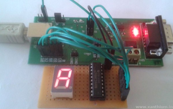
We covered [Anders Nielsen]’s 65duino project a short while ago, and now he’s back with an update video showing some more details of bit-banging I2C using plain old 6502 assembly language.

Obviously, with such a simple system, there is no dedicated I2C interface hardware, so the programmer must take care of all the details of the I2C protocol in software, bit-banging it out to the peripheral and reading back the response one bit at a time.

The first detail to concern us will be the I2C addresses of the devices being connected to the bus and how low-level bit manipulation is used to turn the 7-bit I2C address into the byte being bit-banged. As [Anders] shows
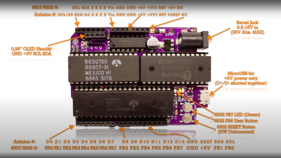
, setting a bit is simply a logical-OR operation, and resetting a bit is a simple logical-AND operation using the inversion (or one’s complement) bit to reset to form a bitmask. As many will already know, this process is necessary to code for a read or a write I2C operation. A further detail is that I2C uses an open-collector connection scheme, which means that no device on the bus may drive the bus to logical high; instead, they must release the drive by going to the high impedance state, and an external pull-up resistor will pull the bus high. The 6532 RIOT chip (used for I/O on the 65unio) does not have tristate control but instead uses a data direction register (DDR) to allow a pin to be an input. This will do the job just fine, albeit with slightly odd-looking code, until you know what’s going on.

From there, it’s a straightforward matter to write subroutines that generate the I2C start, stop, and NACK conditions that are required to write to the SSD1306-based OLED to get it to do something we can observe. From these basic roots, through higher-level subroutines, a complete OLED library in assembly can be constructed. We shall sit tight and await where [Anders] goes next with this!

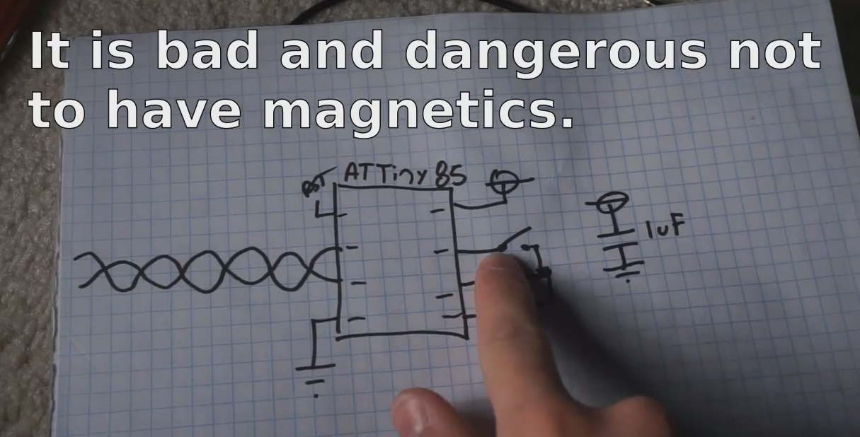
We see I2C-connected things all the time, like this neat ATtiny85-based I2C peripheral, and whilst we’re talking about the SSD1306 OLED display controller, here’s a hack that shows just how much you can push your luck with the I2C spec and get some crazy frame rates.

Continue reading “A Simple Guide To Bit Banged I2C On The 6502”

Arduino CLI For I/O Pin Testing

Need to quickly toggle or read some logic signals without the hassle of writing a quick program? [Thor_x86], aka [Eric], built an Arduino sketch that does just that — and he threw in the ability to send (or receive) serial messages, too. This is a neat idea — kind of a simplified Bus Pirate.

We should warn you that this is an early release, and there are a few minor issues which we are sure [Eric] will iron out soon. We discovered the function strtol() was misspelled in cmd_send.cpp, and there are some configuration #defines which need to be sorted out in file parsePin.cpp, depending on which Arduino module you are running. We got it running on an Arduino Leonardo the quickest, because it has support for Serial1().

Don’t be discouraged by these glitches in this rev 0 deployment — [Eric] has really made quite a nice tool here. Check his GitHub repository for updates (or submit corrections yourself). All in all, it’s a good addition to your digital tool box. On a completely unrelated note, we really like [Eric]’s USB cable with the right-angle micro connector, grungy though it may be.

Besides the standard tools like Bus Pirate, GreatFET, FTDI modules, etc., are there any similar tools you like to use for bit banging and serial testing? Let us know in the comments below.

Driving A 7 Segment LED Display From An FT232

Sometimes, a good hack is about using less rather than more. That’s the case with this neat tutorial from [Rahul.S] on driving a 7-segment LED display with an FT232. By using this cheap USB to serial controller, [Rahul.S] was able to drive the display directly without using a microcontroller, which keeps the component cost down.

He’s bit banging an octal buffer connected to the display. You may be surprised to find that the FT232 chips do have enough outputs to make this work. Rather than send serial data number to the display and have a controller convert this into a set of signals that make the number, this conversion is done by the PC, which then sends a signal that directly illuminates the appropriate parts of the LED. By using all of the available output lines of the FT232 (including ones like the RTS/CTS line that are usually used for signalling), [Rahul.S] was able to drive all seven of the elements and the decimal point.

Of course, cynics may argue that it would be simpler to use a cheap serial LCD display. That is true, but there is always something to be said for knowing how to do something yourself rather than letting others do it for you… Continue reading “Driving A 7 Segment LED Display From An FT232”

Bit-banging Ethernet On An ATTiny85

Ethernet bit banging

[Cnlohr] just published an ingenious but dangerous way to send Ethernet packets using an ATTiny85. The ATtiny directly drives one pair of differential TX wires of a standard Ethernet cable. Doing so will force the TX signal ground to be the same as the ATTiny’s and in some cases may put 48V on your AVR if your cable is plugged into a Power Over Ethernet switch… which may be a problem.

In the video embedded below [cnlhor] explains that the microcontroller is clocked at 20Mhz to bit-bang the Manchester encoded electrical signals. Using a neat trick his home switch will detect his platform as a 10MBit Ethernet switch which can then send hard-coded packets to his computer. As you can guess, each of this packets takes quite a bit of space inside the ATTiny’s flash memory: 2+Kbytes. All of the code used may be downloaded on the creator’s GitHub repository, though he constantly warned us that it shouldn’t be used for real life applications.

Edit: One of our readers also let us know of a similar awesome project called the IgorPlug-UDP. Make sure to check it out!

Continue reading “Bit-banging Ethernet On An ATTiny85”

Learn JTAG By Writing A Bit-banging Programmer

j-tag-flow-chart

[Pesco] won one of Dangerous Prototypes’ PCB giveaways a few months ago. He opted for a CPLD breakout board. He just needed to put in a parts order and populate the components himself. But then what? He needed a JTAG programmer to work with the chip. Like any good autodidact he choose to make his own rather than buying one. He absorbed the JTAG specification and coded a bit banging programmer using an Arduino.

We’ve used JTAG many times to program ARM chips. But until now we never took the time to figure out how the specification works. If you’ve got an IEEE subscription you can download the whitepaper, but [Pesco] was also able to find one floating around on the interwebs. The flow chart on the left is the cheat sheet he put together based on his readings. From there he wrote the Arduino sketch which implements the programming standard, allowing him to interact with a chip through a minicom terminal window.

[via Dangerous Prototypes]

Bit Banging Through A USB Parallel Port Adapter

If you’ve ever looked into low-level parallel port access you may have learned that it only works with actual parallel port hardware, and not with USB parallel port adapters. But here’s a solution that will change your thinking. It borrows from the way printers communicate to allow USB to parallel port bit banging without a microcontroller (dead link, try Internet Archive).

Sure, adding a microcontroller would make this dead simple. All you need to do is program the chip to emulate the printer’s end of the communications scheme. But that’s not the approach taken here. Instead the USB to RS232 (serial) converter also pictured above is used as a reset signal. The strobe pin on the parallel port drives an inverter which triggers a thyristor connected to the busy pin. Thyristors are bistable switches so this solution alone will never clear the busy pin. That’s where the serial connection comes into play. By alternating the data transmitted from the computer between the bit-bang values sent to LP0 and 0xF0 sent to the serial connector the eight parallel data bits become fully addressable. See the project in action in the clip after the break.

Bit Banging VGA From An SD Card Slot

If you’ve got some favorite electronic device that includes an SD card slot but doesn’t have a video out port you may be able to push VGA signals through the card reader conductors. That’s exactly what’s going on above with the Ben NanoNote, a sub-$100 Linux device which we’ve seen using its SD card slot as general I/O before.

The hardware to capture the signals includes a breakout board for the card slot. Free-formed on the other end of that connector card is a gaggle of resistor which handle level conversion for the VGA color signals, with a VGA cable taking it from there to the monitor. The software that makes this happen is a dirty hack, blocking all other functions while it displays a still image. But we’re sure that it can be cleaned up somewhat. Just don’t hold out hopes for full-motion video, this little guy just doesn’t have it in him.

[via Dangerous Prototypes via Slashdot]