Need A Small, Cheap Ammeter? Blinkenlights To The Rescue!

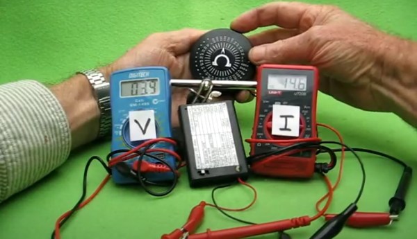
You know how it is. You’ve got that new project running, and while it doesn’t consume much power, it also doesn’t give much indication of whether it’s functioning or just sitting there with a dead battery. What you need is an ammeter to check power consumption, even from across the room. And it just so happens that [Manuka] has Just The Circuit You Need, complete with a demonstration in the video after the break!

Oh sure, you could grab a cheap ammeter at your favorite tool import store or site, but those are bulky and take batteries. You could put in an LED that gets dimmer as voltage drops. But wait- is that the sun shining on it? or is it on? Or has something gone awry and it’s consuming too much power?

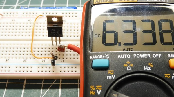
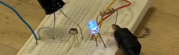
What [Manuka] gives us is a circuit that is designed to be built into your project or project’s power supply. Using only an ultra-bright white LED, red blinking LED, PNP transistor, and a diode, the circuit gives a strong visual indication of current consumption by blinking brighter and more frequently as current increases. With a bit of calibration, accurate measurements can be obtained. All of this is made possible by using the Flashing LED as a driver for the ultra-bright LED, which is a pretty slick hack!

Flashing LEDs have a great number of uses, like protecting your family from lions. Yes, really. Got a cool tip for flashing LEDs, blinkenlights, 555’s, or any odd thing that strikes your hackers fancy? Let the tip line know!

Continue reading “Need A Small, Cheap Ammeter? Blinkenlights To The Rescue!”

A 7805 Regulator puts out 6.3 Volts

Simple Electronic Hacks Inspire Doing More With Less

It’s late at night. The solder smoke keeps getting in your tired eyes, but your project is nearly done. The main circuit is powered by your 13.8 V bench supply, but part of the circuit needs 9 V. You dig into your stash to find your last LM7809 voltage regulator, but all you have is a bunch of LM7805’s. Are you done for the night? Not if you’ve watched [0033mer]’s Simple Electronic Circuit Hacks video! You know just what to do. The ground pin of a LM7805 connects to the cathode of a TL431 programmable Zener diode pulled from an old scrapped TV. The diode is referenced to a voltage divider, and voila! Your LM7805 is now putting out a steady 9 V.

How did [0033mer] become adept at doing more with less? As he explains in the video below, his primary source of parts in The Time Before The Internet was old TV’s that were beyond repair. Using N-Channel MOSFETs to switch AC, sensing temperature changes with signal diodes, and even replacing a 555 with a blinking LED are just a few of the hacks covered in the video below the break.

We especially appreciated the simple, to-the-point presentation that inspires us to keep on hacking in the truest sense: Doing more with less! If you enjoy a good diode hack like we do, you will likely appreciate learning Diode Basics by W2AEW, or a Diode Based Radiation Detector.

Thank you [DSM] for the tip! Be sure to submit your the cool things you come across to our Tips Line!

Continue reading “Simple Electronic Hacks Inspire Doing More With Less”

Another Blinky Light Project — With A COVID-19 Twist

It seems all anyone is talking about right now is the virus scare that has most of us with a little extra time on our hands. [Paul Klinger] — a name we’ve seen before — built a blinking LED project to pass the time. So what? Well, the lights are made to look like a SARS-CoV-2 virus and the LEDs blink the virus RNA code. You can see the results in the video below.

This isn’t very surprising when you consider we’ve seen [Paul] make tiny things and even blink out his own DNA, so he’s clearly got some specific interests in this area.

Continue reading “Another Blinky Light Project — With A COVID-19 Twist”

Freeforming The Atari Punk Console

This stunning piece of art is [Emily Velasco’s] take on the Atari Punk Console. It’s a freeform circuit that synthesizes sound using 555 timers. The circuit has been around for a long time, but her fabrication is completely new and simply incredible!

This isn’t [Emily’s] first rodeo. She previously built the mini CRT sculpture project seen to the left in the image above. Its centerpiece is a tiny CRT from an old video camera viewfinder, and it is fairly common for the driver circuit to understand composite video. And unlike CRTs, small video cameras with composite video output are easily available today for not much money. Together they bring a piece of 1980s-era video equipment into the modern selfie age. The cubic frame holding everything together is also the ground plane, but its main purpose is to give us an unimpeded view. We can admire the detail on this CRT and its accompanying circuitry representing 1982 state of the art in miniaturized consumer electronics. (And yes, high voltage components are safely insulated. Just don’t poke your finger under anything.)

With the experience gained from building that electrically simple brass frame, [Emily] then stepped up the difficulty for her follow-up project. It started with a sound synthesizer circuit built around a pair of 555 timers, popularized in the 1980s and nicknamed the Atari Punk Console. Since APC is a popular circuit found in several other Hackaday-featured projects, [Emily] decided she needed to add something else to stand out. Thus in addition to building her circuit in three-dimensional brass, two photocells were incorporated to give it rudimentary vision into its environment. Stimulus for this now light-sensitive APC were provided in the form of a RGB LED. One with a self-contained circuit to cycle through various colors and blinking patterns.

These two projects neatly bookend the range of roles brass rods can take in your own creations. From a simple frame that stays out of the way to being the central nervous system. While our Circuit Sculpture Contest judges may put emphasis the latter, both are equally valid ways to present something that is aesthetic in addition to being functional. Brass, copper, and wood are a refreshing change of pace from our standard materials of 3D-printed plastic and FR4 PCB. Go forth and explore what you can do!

Continue reading “Freeforming The Atari Punk Console”

Morse Code Blinking Jewelry

With the size of electronic parts and batteries these days, very small items are obviously becoming more and more viable. [Yann Guidon] has made some awesome pieces of LED jewelry using a minimal number of surface mount parts and a small lithium-ion battery. To make the jewelry stand out a bit, other than just blinking on and off, these LEDs blink a short message in Morse code.

This is an update and open sourcing of some work that [Yann] did a few years ago, and the iterations have resulted in a smaller design. But the main part of the latest version is the addition of the Morse code blinking using a small microcontroller. The microcontroller [Yann] used is the SMD version of the PIC10F200, a small, 8 pin PIC microcontroller. This, a resistor and a metal clip are soldered to pads on a Luxeon Star LED.  The LEDs are undervolted so they’re not too bright, so the heat sink isn’t really needed, but it’s a good size for the components. Because the LEDs don’t generation much heat, the back of the aluminum frame that the LED is on is carved out a bit so that the small lithium-ion battery can go there.

The final component is the code itself, and [Yann] has released it as an assembly file. An associated text file contains the text of the message that you want the earrings to blink. The text file can contain up to 190 bytes. A shell script converts the text to a file that can be included in the asm file. After that script is run, assemble the code and flash it to the PIC and you’re done!

We’ve seen a couple of other LED jewelry projects done, including this LED engagement ring, and these tiny light-up earrings. You can see video of [Yann]’s project in the video below:
Continue reading “Morse Code Blinking Jewelry”

A Vintage Single Transistor LED Blinker

[Eric Wasatonic] had a box of SWB2433 transistors that he had very little information about. In order to discover their properties, he fired up his curve tracer to compare these transistors with more common ones. He noticed the SWB2433 exhibited negative resistance while the similar curves of a 2n3904 didn’t. Then he reverse-biased the two transistors: the negative resistance region on the 2n3904 was less than that of the SWB2433, but it was there, and a 2n2222 had a bigger region. Using this knowledge, he developed a relaxation oscillator circuit which uses a negatively biased transistor.

Using one transistor, one resistor and one capacitor, he describes the circuit and how the components affect the frequency of the sawtooth wave the oscillator creates. [Eric] uses the oscillator to build a simple LED blinker and shows what happens when he changes the transistor and adjusts the voltage or resistance. He also shows the circuit as a tone generator and adjusts the tone by replacing the resistor with a potentiometer. And then, for fun, he modifies the circuit to show the oscillator as an AM transmitter. Check out his video after the break.

Continue reading “A Vintage Single Transistor LED Blinker”

Soldering Challenge To Challenge You

[Rick] knew that the blinking, beeping microcontroller kits that are commonly used for educational soldering workshops just would not cut it for a serious combat among SMD reworking professionals. The “Soldering Challenge” he created to fill this gap is a little PCB with eight difficulty levels from large through hole components to the smallest hand solderable SMDs. After assembly, the circuit assesses the skill level of the soldering aspirant based on a built-in scoring system.

soldering_challenge_ongoingThe challenge is meant to be played on a time limit. There are no two same-sized components of different value, so contestants may focus on soldering fast. Little rubber pads on the backside of the board provide for good ground contact in the curves. After the starting signal, you will be confronted with a few through hole resistors, a capacitor, different LEDs and a DIP-8 IC. Here it’s all about the speed and efficiency as you tackle a track full of bends and cut-off resistor legs. Over the course of the challenge, the components get smaller and smaller, until you finally reach the 0603 level, with a tiny SC-85 MOS-FET and a TSSOP 555 timer at the finishing line.
Continue reading “Soldering Challenge To Challenge You”