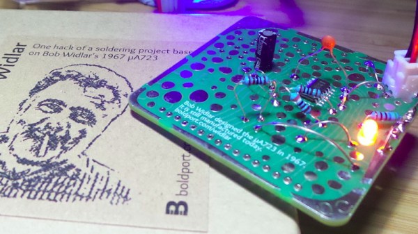
Regular Hackaday readers will be familiar with the work of Boldport’s [Saar Drimer] in creating beauty in printed circuit board design. A recent work of his is the Widlar, a tribute to the legendary integrated circuit designer [Bob Widlar] in the form of a development board for his μA723 voltage regulator chip.
The μA723 is a kit of parts from which almost any regulator configuration can be made, but for [tardate] it represented a challenge. The μA723 is so versatile that what you can create is only limited by the imagination of the builder. Having done the ordinary before, [tardate] looked toward something unconventional.
The result is modest, a simple LED flasher using the error amplifier as a not-very-good op-amp, building an oscillator at a frequency of about 2 Hz. This is pretty neat and if you are used to the NE555 as the universal integrated circuit, perhaps it’s time to set it aside for the obviously far-more-useful μA723.
If you are an electronic engineer or received an education in electronics that went beyond the very basics, there is a good chance that you will be familiar with the Fairchild μA723. This chip designed by the legendary Bob Widlar and released in 1967 is a kit-of-parts for building all sorts of voltage regulators. Aside from being a very useful device, it may owe some of its long life to appearing as a teaching example in Paul Horowitz and Winfield Hill’s seminal text, The Art Of Electronics. It’s a favourite chip of mine, and I have written about it extensively both on these pages and elsewhere.
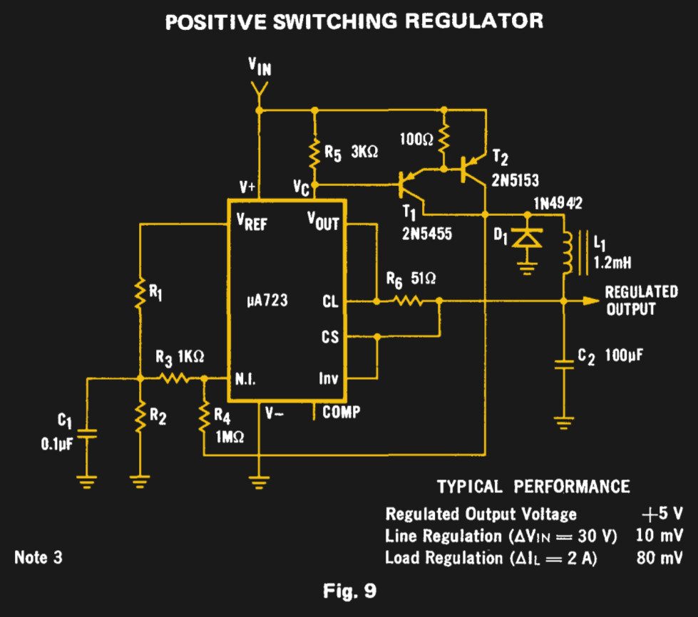
The Fairchild switching regulator circuit. From the μA723 data sheet in their 1973 linear IC databook, page 194 onwards.
For all my experimenting with a μA723 over the decades there is one intriguing circuit on its data sheet that I have never had the opportunity to build. Figure 9 on the original Fairchild data sheet is a switching regulator, a buck converter using a pair of PNP transistors along with the diode and inductor you would expect. Its performance will almost certainly be eclipsed by a multitude of more recent dedicated converter chips, but it remains the one μA723 circuit I have never built. Clearly something must be done to rectify this situation.
“Chapter 5; Horowitz and Hill”. University students of all subjects will each have their standard texts of which everyone will own a copy. It will be so familiar to them as to be referred to by its author as a shorthand, and depending on the subject and the tome in question it will be either universally loathed or held onto and treasured as a lifetime work of reference.
For electronic engineers the work that most exemplifies this is [Paul Horowitz] and [Winfield Hill]’s The Art Of Electronics. It definitely falls into the latter category of course books, being both a mine of information and presented in an extremely accessible style. It’s now available in its third edition, but the copy in front of me is a first edition printed some time in the mid 1980s.
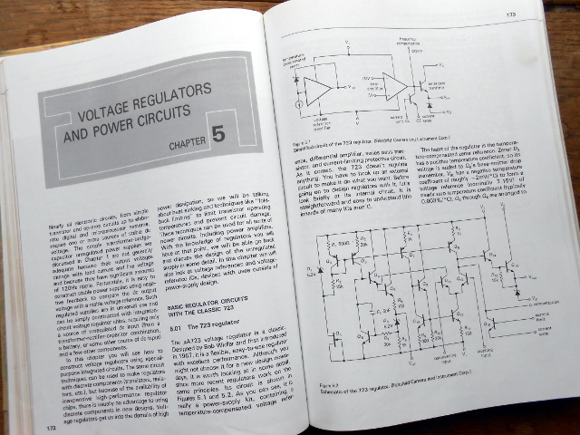
The Art of Electronics, on regulators.
Chapter 5 probably made most of an impression on the late-teenage me, because it explains voltage regulation and power supplies both linear and switching. Though there is nothing spectacularly challenging about a power supply from the perspective of experience, having them explained as a nineteen-year-old by a book that made sense because it told you all the stuff you needed to know rather than just what a school exam syllabus demanded you should know was a revelation.
On the first page of my Art of Electronics chapter 5, they dive straight in to the μA723 linear voltage regulator. This is pretty old; a design from the legendary [Bob Widlar], master of analogue integrated circuits, which first made it to market in 1967. [Horowitz] and [Hill] say “Although you might not choose it for a new design nowadays, it is worth looking at in some detail, since more recent regulators work on the same principles“. It was 13 years old when they wrote that sentence and now it is nearly 50 years old, yet judging by the fact that Texas Instruments still lists it as an active product without any of those ominous warnings about end-of-life it seems plenty of designers have not heeded those words.
So why is a 50-year-old regulator chip still an active product? There is a huge range of better regulators, probably cheaper and more efficient regulators that make its 14-pin DIP seem very dated indeed. The answer is that it’s an incredibly useful part because it does not present you with a regulator as such, instead it’s a kit of all the parts required to make a regulator of almost any description. Thus it is both an astonishingly versatile device for a designer and the ideal platform for anyone wanting to learn about or experiment with a regulator. Continue reading “Get To Know Voltage Regulators With A 723”→
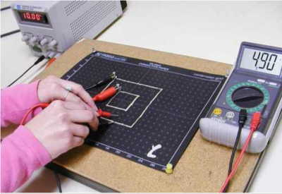
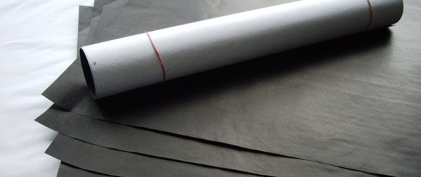
Legendary electrical engineer and linear IC trailblazer Bob Widlar was just like you. What I mean is that he would use everything available to him to mock up circuits, create prototypes, and make things work. One of the simplest and coolest tools he used was a conductive paper called Teledeltos. This wonderful stuff allowed him to define and test various configurations for the oddly-shaped ballast resistors he used in some of his high-performance circuit designs. But it wasn’t created for people like you and Bob. Teledeltos paper was created and trademarked by communications giant Western Union to drastically improve the convenience of telegrams.
Development of the electric telegraph ushered in the era of global communication. Suddenly, people could send messages to the other side of the world in a fraction of the time it took by post. The telegraph absolutely revolutionized human communication. It was the e-mail and the Twitter of its time. The telegraph’s efficiency made the Pony Express pretty much obsolete by the 1860s. And for a very long time it was much cheaper for people to send a telegram than make a long-distance phone call.
The Advantages of Facsimile
Translated from ancient Greek, ‘teledeltos’ basically means writing tablet at a distance. Western Union began developing Teledeltos paper in the 1930s for the purpose of transmitting telegrams by facsimile, a method that would greatly reduce the time it took to input messages into the system and get them out on the other side. As long as both the sender and the receiver had facsimile machines, a handwritten telegram could be transmitted without having to be typed by a clerk or translated into code. Teledeltos paper was also used in a variety of chart recorders, like seismographs and map plotters. The ability to feed a handwritten message, a photograph, or a map of enemy territory into a machine that transmitted an exact copy was a real game changer.
Because of its composition, Teledeltos paper could be easily marked without an electrolyte. It marked so well that photographs and other graphic information could be transmitted, and no processing was required on the receiving end. A dry recording paper is also much less sensitive to light and to temperature extremes. More importantly, properly stored dry paper is impervious to fungal growth. Teledeltos paper could sit around indefinitely without becoming useless. The only real disadvantage to this type of paper was the somewhat laborious process that went into achieving the desired resistance. Fax machines eventually moved on to digital transmission and thermal printing technology.
Teledeltos paper has a light gray electro-sensitive coating on one side, and the other side is carbon black. When a current is applied with a stylus to the coated side of the paper, the coating is instantly burned away, revealing the carbon black. Teledeltos paper could be marked using either AC or DC. Polarity didn’t matter, either, but the boys in the lab at Western Union had better luck when they used a positive stylus with DC rather than a negative one.
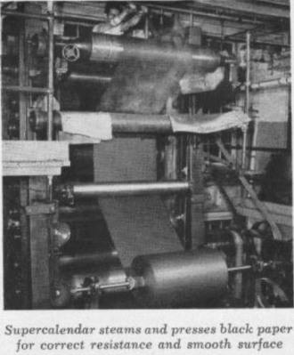
Teledeltos paper was made in two types—“L” for low resistance and “H” for high. The resistivity of a roll of Teledeltos paper depended on the quality of the conductive fibers that went into it. The paper’s electrical characteristics were also influenced by the fiber beating process and the distribution of the conductive fibers by the supercalender, a system of hard rollers used in papermaking and other processes that press and smooth paper and other materials to increase the density.
Teledeltos to the Rescue
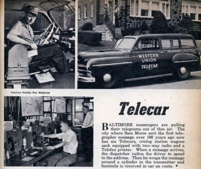
The Western Union Telecar printed telegrams on the go and delivered them to homes and businesses. Image credit: Modern Mechanix
Western Union was eager to extend its reach into private businesses and public places so that patrons who weren’t heavy telegram users didn’t have to visit a telegram office in order to share a bit of good news or to send their condolences. The company’s Telefax division came up with several types of machines to serve different business needs.
Some messages continued to be delivered by hand, but they weren’t printed at the central office. Western Union created a Telecar service to print telegrams transmitted to the car by the central office and deliver them to people’s homes. Messages were printed onto recording blanks that were cut automatically by a Telefax recorder situated in the car’s passenger area. The Telecar’s radio and amplification equipment was in the trunk.
The standard Telefax machine for office use was fairly large, like an early microwave oven. A smaller version called the DeskFax was only about the size of a breadbox, and these units occupied the desks of many businessmen and secretaries because of their convenience.
A Western Union DeskFax unit. Image from [B. Hilpert]Both the Telefax and the DeskFax scanned and recorded telegrams using a rotary drum mechanism. A message could either be typed or handwritten onto a telegram blank. The sender then wrapped the telegram around a drum and set the machine to send. The machine would scan the message optically and then transmit it to the central office.
Before sending it on to the recipient, an attendant at the telegram office had to remove the incoming message and wrap it around the drum of a transmitting machine. Once connected to the receiving party’s line, the far end unit would buzz to arouse attention. The receiving patron would then load a blank on to their DeskFax’s roller and set their machine to receive.
Conductive paper like Teledeltos has many applications aside from fax machines and Fathometers. For starters, it’s great for making one-offs of both standard and variable resistors. Conductive paint can be used as connection points for wires. The paper is also well-suited for simulating current flow through circuits using a fraction of the current intended in production. Vacuum tube designers used Teledeltos for modeling potentials. Teledeltos can also be used to visualize electromagnetic potentials and perform field plotting.
We’re sure that at least a few of our readers out there used Teledeltos or something like it in school or on the job. Did you know you can still buy it? Teledeltos paper itself is still available from two companies in the UK, Better Equipped and Timstar. In the US, you can get it from Pasco in packs of 50 and 100 sheets, with and without a grid pattern.
[Teledeltos paper image is a product photo from Better Equipped]
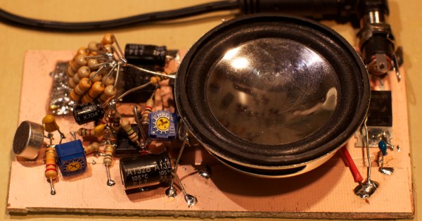
[Craig] recently built himself a version of the “hassler” circuit as a sort of homage to Bob Widlar. If you haven’t heard of Bob Widlar, he was a key person involved in making analog IC’s a reality. We’ve actually covered the topic in-depth in the past. The hassler circuit is a simple but ingenious office prank. The idea is that the circuit emits a very high frequency tone, but only when the noise level in the room reaches a certain threshold. If your coworkers become too noisy, they will suddenly notice a ringing in their ears. When they stop talking to identify the source, the noise goes away. The desired result is to get your coworkers to shut the hell up.
[Craig] couldn’t find any published schematics for the original circuit, but he managed to build his own version with discrete components and IC’s. Sound first enters the circuit via a small electret microphone. The signal is then amplified, half-wave rectified, and run through a low pass filter. The gain from the microphone is configurable via a trim pot. A capacitor converts the output into a flat DC voltage.
The signal then gets passed to a relaxation oscillator circuit. This circuit creates a signal whose output duty cycle is dependent on the input voltage. The higher the input voltage, the longer the duty cycle, and the lower the frequency. The resulting signal is sent to a small speaker for output. The speaker is also controlled by a Schmitt trigger. This prevents the speaker from being powered until the voltage reaches a certain threshold, thus saving energy. The whole circuit is soldered together dead bug style and mounted to a copper clad board.
When the room is quiet, the input voltage is low. The output frequency is high enough that it is out of the range of human hearing. As the room slowly gets louder, the voltage increases and the output frequency lowers. Eventually it reaches the outer limits of human hearing and people in the room take notice. The video below walks step by step through the circuit. Continue reading “Annoy Your Enemies With The Hassler Circuit”→
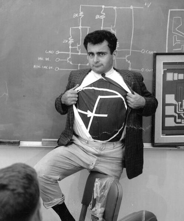
Bob Widlar (1937-1991) is without a doubt one of the most famous hardware engineers of all time. In fact, it would not be an exaggeration to say that he is the person who single-handedly started the whole Analog IC Industry. Sure, it’s Robert Noyce and Jack Kilby who invented the concept of Integrated Circuits, but it’s Widlar’s genius and pragmatism that brought it to life. Though he was not first to realize the limitations of planar process and designing ICs like discrete circuits, he was the first one to provide an actual solution – µA702, the first linear IC Operational Amplifier. Combining his engineering genius, understanding of economic aspects of circuit design and awareness of medium and process limitations, he and Dave Talbert ruled the world of Analog ICs throughout the 60s and 70s. For a significant period of time, they were responsible more than 80 percent of all linear circuits made and sold in the entire world.
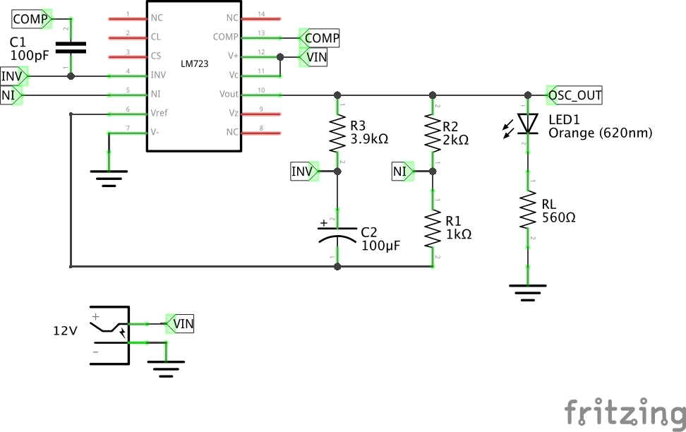 The result is modest, a simple LED flasher using the error amplifier as a not-very-good op-amp, building an oscillator at a frequency of about 2 Hz. This is pretty neat and if you are used to the NE555 as the universal integrated circuit, perhaps it’s time to set it aside for the obviously far-more-useful μA723.
![A Western Union DeskFax unit. Image from [B. Hilpert]http://www.cs.ubc.ca/~hilpert/e/deskfax/](https://hackaday.com/wp-content/uploads/2015/09/deskfax.jpg?w=400)