Reworking MT3608 Boost Converters For Lower Idle Current Draw

The MT3608 is a popular boost converter, able to easily step up DC voltages in useful ranges, at an incredibly low cost. Modules can be sourced from eBay for less than $2, built on a PCB, ready to go. One drawback of these modules, particularly when working with batteries, is the idle current draw, on the order of 1 to 1.5mA. Fear not, however — there is a workaround, courtesy of [Aka Kasyan]. (Video, embedded below.)

The trick is to modify the behavior of the converter when no load is connected. The enable pin of the boost converter is held low through a pull-down resistor, keeping the boost converter switched off. In this state, the output voltage is equal to the input voltage. A current sense resistor is then installed in the output path. When a load is connected, this causes a voltage drop across the current sense resistor. This is then used to switch a transistor, which then connects the enable pin to the positive rail, switching the converter on, leading to the full boosted output voltage being reached.

[Aya] reports that this drastically cuts the idle current draw, which is particularly useful for battery powered projects. It’s important to note that the current sense resistor must be appropriately sized for the given load, however. If you’re a little hazy on the background, fear not — we’ve discussed the nature of boost converters before. Video after the break.

[Thanks to Baldpower for the tip!]
Continue reading “Reworking MT3608 Boost Converters For Lower Idle Current Draw”

Building A 3D Printer That Goes Where You Do

Back when one of the best paths to desktop 3D printer ownership was building the thing yourself from laser cut wood with some string thrown in for good measure, just saying you had one at home would instantly boost your hacker street cred. It didn’t even need to work particularly well (which is good, since it probably didn’t), you just had to have one. But now that 3D printers have become so common, the game has changed. If you want to keep on the cutting edge, you’ve got to come up with a unique hook.

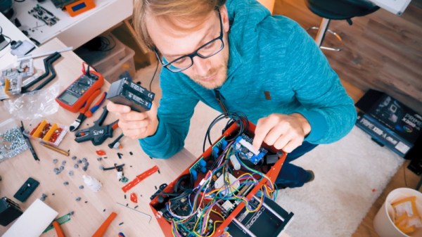
Luckily for us, [Thomas Sanladerer] is here to advance the status quo of desktop 3D printing. Not content with a 3D printer that spends its time loafing around the workshop, he decided to build a completely mobile 3D printer. For a guy who spends a lot of time traveling to different 3D printing conferences and shows, this is actually a pretty handy thing to have around, but there are probably some lessons to be learned here even if you aren’t a 3D printing YouTube celebrity.

Given the wide array of very popular low cost 3D printers out there, some will likely be surprised that [Thomas] decided to mobilize a printer which is nearly an antique at this point: the PrinterBot Play. But as he explains in the video after the break, the design of the Play really lends itself perfectly to life on the road. For one, it’s an extremely rigid printer thanks to its (arguably overkill) steel construction. Compared to most contemporary 3D printers which are often little more than a wispy collection of aluminium extrusion and zip ties, the boxy design of the Play also offers ample room inside for additional electronics and wiring

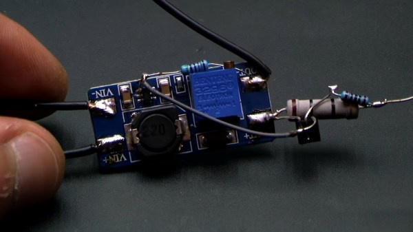
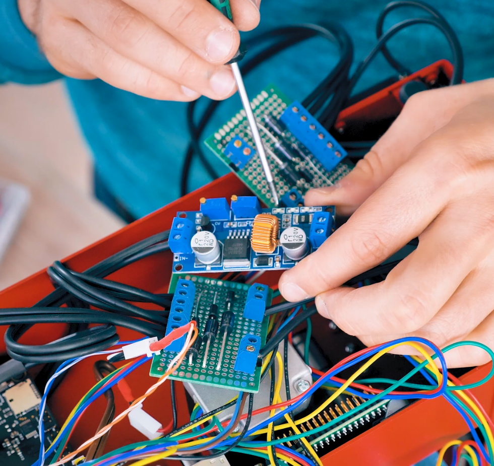
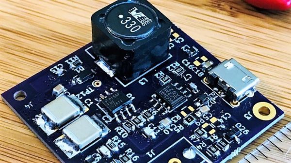
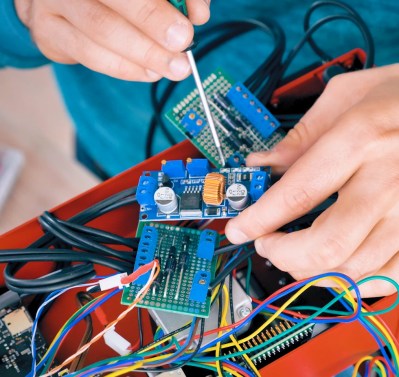
The most obvious addition to the PrintrBot is the six Sony NP-F camera batteries that [Thomas] attaches to the back of the printer by way of 3D printed mounts, but there’s also quite a bit of hardware hidden inside to break the machine free from its alternating current shackles. The bank of batteries feed simultaneously into a DC boost converter which brings the battery voltage up to the 12 V required for the printer’s electronics and motors, and a DC regulator which brings the voltage down to the 5 V required by the Raspberry Pi running OctoPrint. There’s even a charge controller hiding in there which not only frees him from carrying around a separate charger, but lets him top up the cells while the printer is up and running.

On the software side of things, the Raspberry Pi is configured to work as a WiFi access point so that OctoPrint can be controlled with a smartphone even if there’s no existing network in place. A fact demonstrated when he takes the printer outside for a walk while it’s in the middle of a job. The ability to control the printer without any existing infrastructure combined with the estimated six hour runtime on a charge means this modified PrinterBot can get the job done no matter where [Thomas] finds himself.

The hacker community was saddened by the news that PrintrBot was closing its doors last year, an unfortunate casualty of an increasingly competitive desktop 3D printing market. But perhaps we can take some comfort from the fact that their eminently hackable open source printers still live on in projects such as this.

Continue reading “Building A 3D Printer That Goes Where You Do”

Vintage Audio Gear Gets A Display Upgrade

The lengths the retrocomputing devotee must go to in order to breathe new life into old gear can border on the heroic. Tracing down long-discontinued parts, buying multiple copies of the same unit to act as organ donors for the one good machine, and when all else fails, improvising with current productions parts to get that vintage look and feel.

This LCD display backlighting fix for a vintage audio sampler falls into that last category, which was pulled off by [Inkoo Vintage Computer]. The unit in question is an Akai S1100 sampler, a classic from the late 1980s that had already been modified to replace the original floppy drive with a USB reader when the backlight on the LCD began to give out. Replacements for the original electroluminescent backlight are available, but [Inkoo] opted for a cheaper way out. An iPhone 6s 6 Plus backlight was an inexpensive option, if it could be made to fit. Luckily, [Inkoo] was able to trim the diffuser without causing any electrical issues. A boost converter was needed to run the backlight from the sampler’s 5 V DC rail, and interfacing the backlight’s flexible circuitry to the 80s-era copper wiring was a bit fussy, but the results were great. The sampler’s LCD is legible again, and looks just like it might have in the studio back when [Depeche Mode] and [Duran Duran] were using it to crank out hits.

As much as we like this repair, it doesn’t imply that EL is a dead technology. Far from it – [Ben Krasnow] is using it to create unique displays, and EL wire makes for some dazzling wearables. It doesn’t last forever, but while it does, it’s pretty neat stuff.

A Flashlight Powered By Your Hot Little Hands

We are smack-dab in the middle of our Energy Harvesting Challenge, and [wasimashu] might have this one in the palm of his hand. Imagine a compact flashlight that doesn’t need batteries or bulbs. You’d buy a 10-pack and stash them everywhere, right? If there’s nothing that will leak or break or expire in your lifetime, why not have a bunch of them around?

Infinity uses nothing but body heat to power a single white LED. It only needs a five-degree temperature difference between the air and your hand to work, so it should be good in pretty much any environment. While it certainly won’t be the brightest light in your collection, it’s a whole lot better than darkness. Someday, it might be the only light around that works.

As you might expect, there’s a Peltier unit involved. Two of them, actually. Both are embedded flush on opposite sides of the hollow aluminum flashlight body, which acts as a heat sink and allows air to pass through.  After trying to boost the output voltage with a homemade feedback oscillator and hand-wound transformers, [wasimashu] settled on a unipolar boost converter to reach the 5V needed to power the LED.

[wasimashu] has made it his personal mission to help humanity through science. We’d say that Infinity puts him well on the way, and can’t wait to see what he does next.

Supercapacitors In A Servo: The “Forever” Flashlight

The principle is well understood: use a motor in reverse and you get a generator. Using this bit of knowledge back in 2001 is what kick-started [Ted Yapo]’s Hackaday Prize entry. At the time, [Ted] was searching for a small flashlight for astronomy, but didn’t like dealing with dead batteries. He quickly cobbled together a makeshift solution out of some supercapacitors and a servo-as-a-generator, hacked for continuous rotation.

A testament to the supercapacitors, 17 years later it’s still going strong – leading [Ted] to document the project and also improve it. The original circuit was as simple as a servo, protection diode, some supercapacitors, and a LED with accompanying resistor; but now greater things are afoot.

A DC-DC boost converter enables constant power through the LED, regardless of the capacitor voltage. This is achieved by connecting the feedback pin of an MCP1624 switcher to an INA199 current-shunt monitor. The MCP1624 kicks in at 0.65V and stays active down to 0.35V. This is all possible due to the supercapacitors, which happily keep increasing current as voltage drops – all the way to 0.35V. Batteries are less ideal in this situation, as their internal resistance increases as voltage drops, as well as increasing with age.

When testing the new design, [Ted] found that the gears on his servos kept stripping when he was using them to charge capacitors. Though at first he attributed it to the fact that the gears were plastic, he realized that his original prototype from 2001 had been plastic as well. Eventually, he discovered the cause: modern supercapacitors are too good! The ones he’d been using in 2001 were significantly less advanced and had a much higher ESR, limiting the charging current. The only solution is to use metal gear servos

Want to read more about boost converter design? We have the pros and cons of microcontrollers for boost converters, or this neat Nixie driver for USB power.

The Pros And Cons Of Microcontrollers For Boost Converters

It never fails — we post a somewhat simple project using a microcontroller and someone points out that it could have been accomplished better with a 555 timer or discrete transistors or even a couple of vacuum tubes. We welcome the critiques, of course; after all, thoughtful feedback is the point of the comment section. Sometimes the anti-Arduino crowd has a point, but as [Great Scott!] demonstrates with this microcontroller-less boost converter, other times it just makes sense to code your way out of a problem.

Built mainly as a comeback to naysayers on his original boost-converter circuit, which relied on an ATtiny85, [Great Scott!] had to go to considerable lengths to recreate what he did with ease using a microcontroller. He started with a quick demo using a MOSFET driver and a PWM signal from a function generator, which does the job of boosting the voltage, but lacks the feedback needed to control for varying loads.

Ironically relying on a block diagram for a commercial boost controller chip, which is probably the “right” tool for the job he put together the final circuit from a largish handful of components. Two op amps form the oscillator, another is used as a differential amp to monitor the output voltage, and the last one is a used as a comparator to create the PWM signal to control the MOSFET. It works, to be sure, but at the cost of a lot of effort, expense, and perf board real estate. What’s worse, there’s no simple path to adding functionality, like there would be for a microcontroller-based design.

Of course there are circuits where microcontrollers make no sense, but [Great Scott!] makes a good case for boost converters not being one of them if you insist on DIYing. If you’re behind on the basics of DC-DC converters, fear not — we’ve covered that before.

Continue reading “The Pros And Cons Of Microcontrollers For Boost Converters”

Nicely Engineered Boost Converter Powers Nixies From USB Charger

Love them or hate them, Nixies are here to stay. Their enduring appeal is due in no small part to the fact that they’re hardly plug-and-play; generating the high-voltage needed to drive the retro displays is part of their charm. But most Nixie power supplies seem to want 9 volts or more on the input side, which can make integrating them into the typical USB-powered microcontroller project difficult.

Fixing that problem is the idea behind [Mark Smith]’s 5-volt Nixie power supply. The overall goal is simple: 5 volts in, 170 volts out at 20 mA. But [Mark] paid special care to minimize the EMI output of the boost converter through careful design, and he managed to pack everything into a compact 14-cm² PCB. He subjected his initial design to a lot of careful experimentation to verify that he had met his design goals, and then embarked on a little tweaking mission in KiCad to trim the PCB’s footprint down by 27%. The three separate blog posts are well worth a read by anyone interested in learning about electronics design.

Now that [Mark] has his Nixie power supply, what will become of it? We can’t say for sure, but it’ll be a clock. It’s always a clock. Unless it’s a power meter or a speedometer.