Homemade SawStop Attachment Is Just About As Sketchy As It Sounds

TL;DR — when [Colin Furze] is your “safety inspector,” you really should be reconsidering your project goals.

Most of us have probably by now seen the SawStop brand of self-stopping table saw, which detects when something meatier than wood has the bad taste to touch the spinning blade, more or less instantly stopping it and preventing sudden traumatic amputations. It’s an outstanding idea, and we’d love to see the technology built into all table saws. But alas, SawStop saws are priced out of reach for many woodworkers, which left [Ruth Amos] to roll her own DIY version of the system.

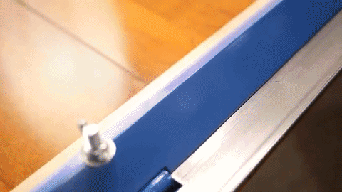
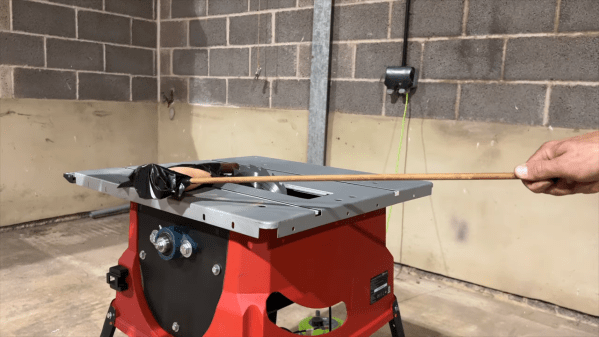
It should be stated right off the bat that none of what [Ruth] does here is a good idea, and that everything shown is really just a proof of concept. The basis for her build was a somewhat flimsy-looking contractor-style saw, to which [Ruth] attached an Arduino set up to detect when something conductive touches the blade. She shares no particulars on the sensing method, but our guess is capacitive coupling. She then sets about experimenting with a series of above-table gizmos to arrest the blade, with limited success, plus all the attachments would make the saw essentially useless. But working above the table does make sense in the prototyping phase, and allowed her to figure out what wouldn’t work.

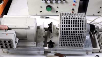
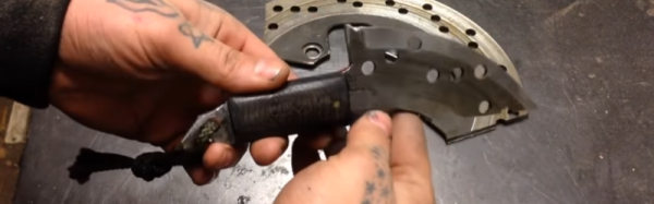
In the end, it was an electromagnetic clutch from an electric lawnmower that seemed to do the trick, albeit at the expense of heavy mods to the saw and a considerable increase in the system’s angular momentum. Nonetheless, the blade stops pretty close to instantly in the old hot dog test. It doesn’t drop the blade below the table, of course, and the hot dog is a little worse for the wear, but it’s still pretty impressive.

We’ve discussed SawStop’s technology before and why it isn’t perhaps as widely available as it should be, if you’re curious.

Continue reading “Homemade SawStop Attachment Is Just About As Sketchy As It Sounds”

Open-Source Farming Robot Now Includes Simulations

Farming is a challenge under even the best of circumstances. Almost all conventional farmers use some combination of tillers, combines, seeders and plows to help get the difficult job done, but for those like [Taylor] who do not farm large industrial monocultures, more specialized tools are needed. While we’ve featured the Acorn open source farming robot before, it’s back now with new and improved features and a simulation mode to help rapidly improve the platform’s software.

The first of the two new physical features includes a fail-safe braking system. Since the robot uses electric geared hub motors for propulsion, the braking system consists of two normally closed relays which short the motor leads in emergency situations. This makes the motors see an extremely high load and stops them from turning. The robot also has been given advanced navigation facilities so that it can follow custom complex routes. And finally, [Taylor] created a simulation mode so that the robot’s entire software stack can be run in Docker and tested inside a simulation without using the actual robot.

For farmers who are looking to buck unsustainable modern agricultural practices while maintaining profitable farms, a platform like Acorn could be invaluable. With the ability to survey, seed, harvest, and even weed, it could perform every task of larger agricultural machinery. Of course, if you want to learn more about it, you can check out our earlier feature on this futuristic farming machine.

Adding Brakes To Actuated Fingers

Building exoskeletons for people is a rapidly growing branch of robotics. Whether it’s improving the natural abilities of humans with added strength or helping those with disabilities, the field has plenty of room for new inventions for the augmentation of humans. One of the latest comes to us from a team out of the University of Chicago who recently demonstrated a method of adding brakes to a robotic glove which gives impressive digital control (PDF warning).

The robotic glove is known as DextrEMS but doesn’t actually move the fingers itself. That is handled by a series of electrodes on the forearm which stimulate the finger muscles using Electrical Muscle Stimulation (EMS), hence the name. The problem with EMS for manipulating fingers is that the precision isn’t that great and it tends to cause oscillations. That’s where the glove comes in: each finger includes a series of ratcheting mechanisms that act as brakes which can position the fingers precisely enough to make intelligible signs in sign language or even play a guitar or piano.

For anyone interested in robotics or exoskeletons, the white paper is worth a read. Adding this level of precision to an exoskeleton that manipulates something as small as the fingers opens up a brave new world of robotics, but if you’re looking for something that operates on the scale of an entire human body, take a look at this full-size strength-multiplying exoskeleton that can help you lift superhuman amounts of weight.

Continue reading “Adding Brakes To Actuated Fingers”

Cheap Electric Scooter Gets A Big Brake Upgrade; Unlocks Proper Drift Mode

The last few years have seen a huge rise in the prominence of electric scooters. Brushless motors, lithium batteries, and scooter sharing companies have brought them to the mainstream. However, electric scooters of a variety of designs have been around for a long time, spawning a dedicated subculture of hackers intent on getting the best out of them.

One such hacker is yours truly, having started by modifying basic kick scooters with a variety of propulsion systems way back in 2009. After growing frustrated with the limitations of creating high-speed rotating assemblies without machine tools, I turned my eye to what was commercially available. With my first engineering paycheck under my belt, I bought myself a Razor E300, and was promptly disappointed by the performance. Naturally, hacking ensued as the lead-acid batteries were jettisoned for lithium replacements.

Over the years, batteries, controllers and even the big old heavy brushed motor were replaced. The basic mechanical layout was sound, making it easy to make changes with simple hand tools. As acceleration became violent and top speeds inched closer to 40 km/h, I began to grow increasingly frustrated with the scooter’s one glaring major flaw. It was time to fix the brakes.

Continue reading “Cheap Electric Scooter Gets A Big Brake Upgrade; Unlocks Proper Drift Mode”

Motor Test Bench Talks The Torque

Salvaging a beefy motor is one life’s greatest pleasures for a hacker, but, when it comes to using it in a new project, the lack of specs and documentation can be frustrating. [The Post Apocalyptic Inventor] has a seemingly endless stockpile of scavenged motors, and decided to do something about the problem.

Once again applying his talent for junk revival, [TPAI] has spent the last year collecting, reverse-engineering and repairing equipment built in the 1970s, to produce a complete electric motor test setup. Parameters such as stall torque, speed under no load, peak power, and more can all easily be found by use of the restored test equipment. Key operating graphs that would normally only be available in a datasheet can also be produced.

The test setup comprises of a number of magnetic particle brakes, combined power supply and control units, a trio of colossal three-phase dummy loads, and a gorgeously vintage power-factor meter.

Motors are coupled via a piece of rubber to a magnetic particle brake. The rubber contains six magnets spaced around its edge, which, combined with a hall sensor,  are used to calculate the motor’s rotational speed. When power is applied to the coil inside the brake, the now magnetised internal powder causes friction between the rotor and the stator, proportional to the current through the coil. In addition to this, the brake can also measure the torque that’s being applied to the motor shaft, which allows the control units to regulate the brake either by speed or torque. An Arduino slurps data from these control units, allowing characteristics to be easily graphed.

If you’re looking for more dynamometer action, last year we featured this neatly designed unit – made by some Cornell students with an impressive level of documentation.

Continue reading “Motor Test Bench Talks The Torque”

Knives Hewn From Brake Discs Past

Knives are tools that rely heavily on material quality to do their job right. A knife made of cheap steel won’t hold an edge well, and blunt knives are more likely to cause injury, or at the least, be more difficult to use. The trick to making a good knife is to start with good material. Disc brakes just so happen to be a great source of cast iron, and are readily available, so [Diesineveryfilm Customs] has machined a knife out of a brake disc.

The first step is to roughly cut out the knife’s form from the disc. It’s easy enough to cut out with an angle grinder, following up with a belt sander to finish up the grip. After sharpening, the sharp blade is taped off for safety while a wooden grip is added. Holes are drilled in the brake rotor, allowing the wooden parts to be pinned and glued together before a trip to the belt sander for shaping. A string and dye are added to the handle as finishing touches.

It’s a great use of high-quality scrap material to produce a useful tool. An earlier disc brake knife video shares some useful techniques of its own – we liked the shortcut of measuring the disc thickness, then using a matching drillbit to mark the centerline for sharpening.

Perhaps your own knives aren’t sharp enough – check out this home-built adjustable sharpening rig.

Home-Made Metal Brake

Sometimes, the appropriate application of force is the necessary action to solve a problem. Inelegant, perhaps, but bending a piece of metal with precision is difficult without a tool for it. That said, where a maker faces a problem, building a solution swiftly follows; and — if you lack a metal brake like YouTuber [makjosher] — building one of your own can be accomplished in short order.

Drawing from numerous online sources, [makjosher]’s brake is built from 1/8″ steel bar, as well as 1/8″ steel angle. The angle is secured to a 3/4″ wood mounting plate. Displaying tenacity in cutting all this metal with only a hacksaw, [makjosher] carved slots out of the steel to mount the hinges, which were originally flush with the wood. He belatedly realized that they needed to be flush with the bending surface. This resulted in some backtracking and re-cutting. [Makjosher] then screwed the pivoting parts to the wood mount. A Box tube serves as a handle. A coat of paint  finished the project, and adding another tool to this maker’s kit.

Continue reading “Home-Made Metal Brake”