SparkFun Gets Back To Their Roots With SparkX

Way back in the before years when there were still interesting concepts for reality TV, Nate Seidle blew up a power supply in his dorm room. Instead of finding replacement parts, Nate decided to start a company. For the last decade and a half, SparkFun has grown immensely, been an incredible resource for makers and engineers alike, and shipped out hundreds of thousands of their iconic red boxes.

Being the CEO of a company means you need to do CEO stuff, and a few summers ago Nate the CEO became Nate the Engineer once again. SparkFun is still doing great, but now we know what Nate has been up to these last months. He’s getting back to SparkFun’s roots with SparkX. This is the newest stuff SparkFun has to offer, there is zero documentation or support, and they’re only developing products because Nate wants to.

In a series of blog posts on the SparkFun blog, Nate goes over what is involved in building a new brand for the latest and greatest SparkFun can produce. This involves setting up the SparkX lab, getting the OtherMills pumping out circuit boards, and  inevitably the occasional containment failure of the blue smoke.

The first product in the SparkX lineup, Product 0, is a breakout board for the MLX90393 magnetometer. This is a pretty nifty magnetometer that Ted Yapo over on hackaday.io has used to characterize magnets. Really, though, the SparkX Product 0 is exactly what it says on the tin: a breakout board that is just an experiment, comes with no guarantees or support. It is the heart of what Sparkfun set out to do twenty years ago.

DIY Optical Sensor Breakout Board Makes DIY Optical Mouse

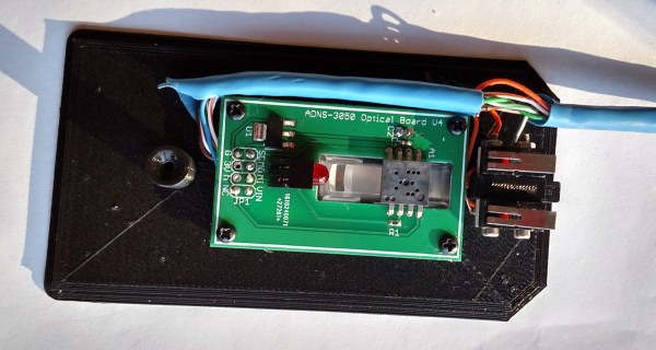
Wanting to experiment with using optical mouse sensors but a bit frustrated with the lack of options, [Tom Wiggins] rolled his own breakout board for the ADNS 3050 optical mouse sensor and in the process of developing it used it to make his own 3D-printed optical mouse. Optical mouse sensors are essentially self-contained cameras that track movement and make it available to a host. To work properly, the sensor needs a lens assembly and appropriate illumination, both of which mate to a specialized bracket along with the sensor. [Tom] found a replacement for the original ADNS LED but still couldn’t find the sensor bracket anywhere, so he designed his own.

Continue reading “DIY Optical Sensor Breakout Board Makes DIY Optical Mouse”

Quad Serial Adapter

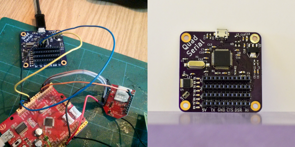
Despite concerted efforts to kill them, serial ports are alive and well, especially in embedded system. True, most of them end in a USB port, these days, but there’s still a lot of gear with a DE-9 (it isn’t a DB-9, despite the common use of the word) or a TTL-serial port lurking around. [James Fowkes] got tired of managing a bunch of USB to serial adapters, so he decided to build his own FT4232 breakout board that would provide four serial ports from a USB connection.

The small board has transmit and receive LEDs for each port along with EMI and ESD protection on the USB port. The ports are all TTL serial, serving the modern hacker, and the 3.3V pins are 5V tolerant.

Continue reading “Quad Serial Adapter”

Smart AC Monitoring: Without The $500 Price Tag

[Tisham Dhar] has been interested in monitoring AC power and previously built a breakout board for the ADE7763. He wanted to find something cheaper and more modern. The ATM90E26 fit the bill. It can communicate via a UART or SPI, and has multiple metering modes. The problem? The evaluation module from Atmel costs about $500 (and for [Dhar] $800 Australian), although the part itself can be had for under a buck in bulk. (Atmel even sent him three samples for free.)

[Dhar] put the low voltage components from the reference design on a PCB and pocketed the difference in cost. So far, he’s tested the setup with a Teensy and low voltage measurements only. He plans to do a full test soon.

The test setup uses SPI mode 3 to talk to the processor. You can find the relevant code on GitHub.

We see a lot of energy monitoring projects go by. Of course, working on household wiring current can be dangerous, so be careful out there.

Truly Versatile ESP8266 WiFi Webcam Platform

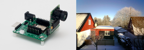
[Johan Kanflo] built a sweet little ESP8266-based wireless camera. It’s a beautiful little setup, and that it’s all open and comes with working demo code is gravy on the cake! Or icing on the potatoes. Or something.

[Johan]’s setup pairs an ESP8266-12 module with an Arducam, which looks like essentially an SPI breakout board for the ubiquitous small CMOS image sensors. The board naturally has a power supply and headers for programming the ESP module as well as connectors galore. Flash in some camera code, and you’ve got a custom WiFi webcam. Pretty slick.

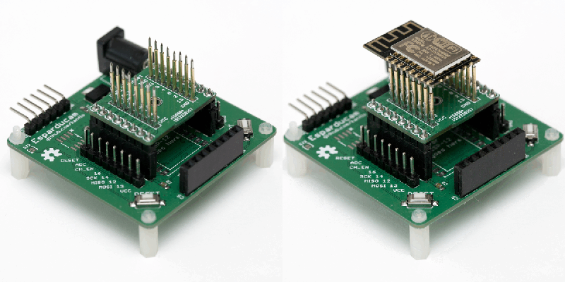
pogo_pin_animBut since [Johan] designed the ESP-8266 board with standard female headers connecting to the ESP, it could also be used as a general-purpose ESP dev board. [Johan] built a few daughterboards to go along with it, including a bed-of-nails ESP8266 tester (since you can never tell when you’re going to get a dud ESP unit) and WiFi-to-RFM69 radio bridge. That’s two awesome applications for a tidy little system, and a reminder to design for extensibility when you’re laying out your own projects.

We’ve previously covered [Johan]’s Skygrazer project, which tracks planes as they fly overhead and displays them on a gutted old Mac. Is it any surprise, then, that he’s also created an ADS-B-controlled moodlight? This guy is on fire!

ESP-Micro Is A Tiny Development Board

The ESP-8266 packs a lot of networking power into a small package. Some would say too small, which is why they often come on a slightly larger carrier PCB. The PCB is usually little more than a breakout with an optional 3.3V regulator. [Frazer Barnes] went one step further: he put an equally tiny USB to serial bridge, an oscillator, and some power management on an ESP-8266 breakout board.

You can program the ESP-8266 via the serial port, so having a built-in USB port is handy. Of course, you might not need it in the final product, but with the board being 25x30mm, you can probably cram it into most projects. [Frazer] posted a bit about the project on Hackaday.io, and has a GitHub project, although right now the upload of the design files is pending.

There’s no shortage of ESP-8266 projects. We saw a small Zigbee to ESP8266 board last year, and also the antidote for a tiny carrier board that includes an LCD, switches, and more. We also have tons of breakouts on Hackaday.io: here’s one with all the bells and whistles, and a similar, stripped-down version. All open-everything, and ready to go.

Organize That Messy Prototype

You’re working away busily at your project. A pcb here cabled to a breadboard in the middle, and over there some motors and other devices. It should work but it doesn’t. Time to hook-up the multimeter but the test point is on the other side. As things are moved around to reach the point, the magic smoke escapes from a critical component. Should have put those pliers away.

Workbenches are always messy. [Ryan Clark] may have an idea that can help.  His Jigmod system — currently running a kickstarter campaign — uses an acrylic a polycarbonate sheet with a grid of mounting holes to keep prototyping hardware in place. If you need to move the prototype around there is no strain on the wiring and no way to set a circuit down on that pair of pliers. The positioning of everything is your decision.

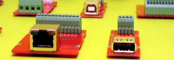
[Ryan] is also providing breakout type boards for connectors like USB and Ethernet, switches, battery holders, and other typical components. This is one place where the system really shines. A lot of these interface connectors tend to be breadboard-unfriendly and the terminal blocks these modules offer solves those issues. When you need to demonstrate your project it’s easy to transport since everything is attached to the plate. No more disconnecting cables, especially jumper wires, and hoping you get them all hooked back the right way at the destination.

With so many dev boards out there we really enjoy seeing jigs that can hold them along with a breadboard. This Stickvise-inspired 3D printed jig sticks out in our minds as a favorite. Do you have your own system of organizing your prototype builds? We’d love to hear about it in the comments!