Starting a design with a new part can be hard. What power supply voltage(s) does it need? Are there any support component requirements? What is the footprint? What about the I/O voltage levels? Breakout boards are designed to answer all those questions for you. Breakouts help when you’re designing with a new part – be it a microcontroller, a sensor, a motor driver, or anything else. They also are a huge help when you’re trying to knock out a quick hack, and just need to get something working quick. Fast to integrate, often breadboard friendly, breakouts just make things easier! This week’s Hacklet is about some of the best breakout board projects on Hackaday.io!
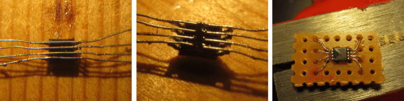
 We start with [Christoph] and STM32F030F4P6 breakout board. Inspired by the Teensy 3.0, [Christoph] set out to build a simple, easy to use, and small breakout board for an ARM processor. The STM32F030F4P6 is a great starting point. At only 20 pins, it’s one of the smallest ARM based chips around. He added the basic things needed to bring this chip up: decoupling caps, a reset button, headers for ST’s software debugger, and of course an LED for a blinky hello world program. The resulting board is physically tiny, but this lilliputian ARM board packs Coretex M0 powered punch!
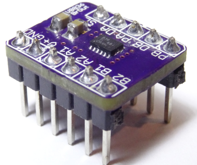 Next up is [al1] and DRV8836 Breakout. Sooner or later, everyone wants to drive a motor in one of their projects. It’s a rite of passage, just like blinking an LED. Motors pull a lot of current though, so external transistors or driver chips are almost always necessary. TI’s DRV8836 chip packs two full H-bridges into one package. That’s enough to drive two DC motors or one stepper. Handling 1.5 amps of current per driver in a tiny package means that thermal coupling is important. The DRV8836 has a large thermal pad which has to be soldered to keep the magic smoke in. [al1] dropped the chip, along with the correct thermal footprint and decoupling capacitors onto a simple breakout. The result is easy to use motor drivers for the masses.
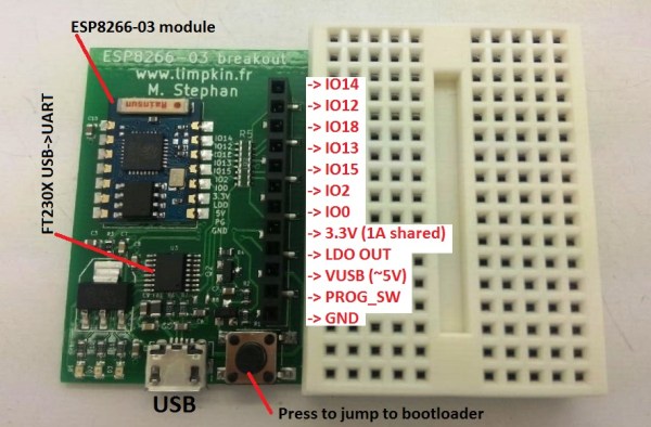
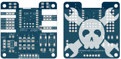 Hackaday.io power user [davedarko] took cues from his favorite designs to create Ignore this ESP8266 board. In [Dave’s] own words, “I stole from every one. The huzza from Adafruit, [Matt’s] breakout board, [Al1s] board, NodeMCUs DevKit.” Hey [Dave] there’s no stealing in open source hardware! There is only design reuse with attribution, which is exactly what you’re doing. [Dave’s] breakout can use both popular ESP8266 footprints: the ESP-01 and ESP-12. He’s added power, reset/programming buttons, and the all important serial header to talk to the module. Going serial allows dave to keep costs down by not including an expensive serial to USB chip in the BOM. Most of us have FTDI cables (or clones) bouncing hanging around anyway. We definitely like the logo on this one!
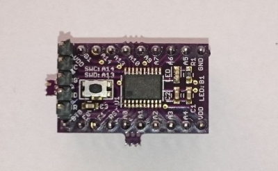
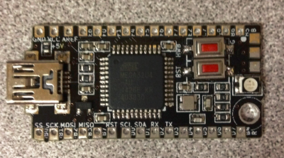 Finally we have [The Big One] with uBBB 32u4. uBBB 32u4 is a bigger brother of µbbb, a Hackaday.io project [Warren] and [The Big One] worked on. µbbb uses an Atmel ATmega32u2 processor. [The Big One] has expanded the faimly to include an ATmega32u4. If you’re wondering, uBBB stands for “Micro Bare Bones Board” At 1.65″ x 0.8″, this is a micro board. It still manages to include everything you need to get the processor up and running fast. Crystal, buttons, decoupling caps, and LEDs – everything is here. A mini USB connector makes communicating with the ATmega a snap!
If you want to see more breakout boards, check out our new breakout board list! If I’ve forgotten to add you to the list, just drop me a message on Hackaday.io. That’s it for this week’s Hacklet, As always, see you next week. Same hack time, same hack channel, bringing you the best of Hackaday.io!